10 rated speed (s100: c1-26) – Yaskawa Varispeed 626M5 User Manual
Page 119
6.4 Constant Settings
6 -13
6.4.10 Rated Speed (S
100
: C1-26)
Set the rated speed to match the machine specifications. The Motor will operate at this rated speed when
the speed reference value input is 100%. The rated speed can be set between 100 min
−1
and the maximum
Motor speed.
6.4.11 Gear Ratios (R
HGR
: C1-27, R
MGR
: C1-28, R
LGR
: C1-29)
Use these constants to set the gear ratio of the Motor shaft and the load shaft according to the machine
specifications. The gear ratio (= load shaft speed/Motor speed) can be set to between 0.0400 and 2.5000.
The set value affects the characteristics during orientation control, so set the accuracy to four decimal
places.
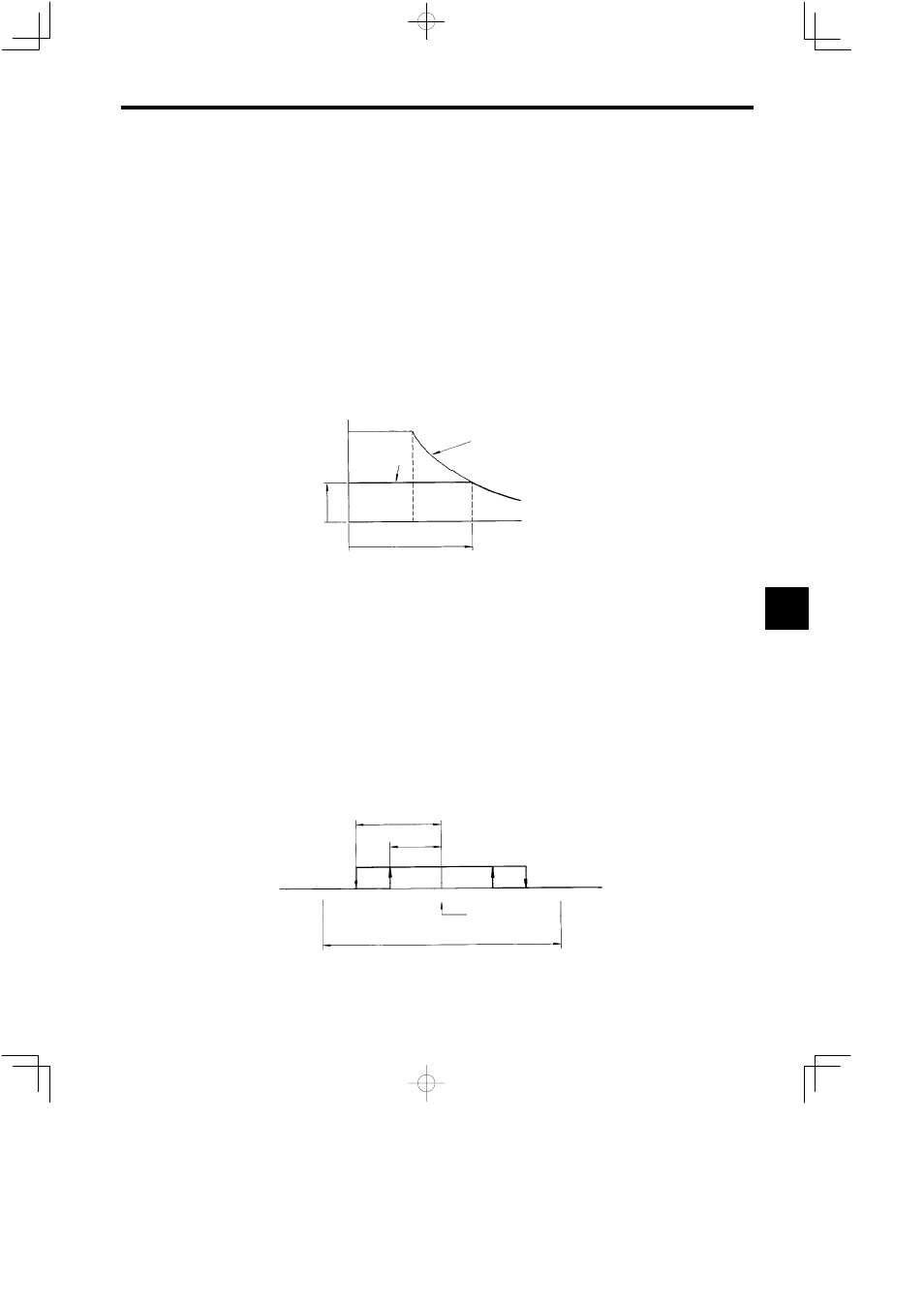
6.4.12 Servo Mode Flux and Base Speed Ratio
(Φ
SVH
: C1-31, R
BSH
: C1-32, Φ
SVL
: C1-33, R
SBL
: C1-34)
Use these control constants when increasing the rated torque control range, such as for a solid tap. As
shown in the following diagram, set the flux level (C1-31 and C1-33) and the base speed ratio (C1-32 and
C1-34) in relation to each other.
Flux
Servo mode
Normal operation
Base speed
Base speed x C1-32
C1-34
(%)
100
C1−31
C1−33
0
Fig 6.8
Servo Mode Flux Level
6.4.13 Positioning Completion Detection Width (Z
FIN
: C2-09 and C3-09) and Posi-
tioning Completion Cancel Width (Z
CAN
: C2-10 and C3-10)
Make sure the Motor is stopped before setting the Positioning Completion Detection Width and Position-
ing Completion Cancel Width. The orientation completion signal turns ON when the deviation between
the stop position reference and the stop position is below the completion detection width for 60 ms or lon-
ger. Also, after the completion signal has been output once, if the deviation is greater than the completion
cancel width, the completion signal will immediately turn OFF.
The encoder orientation control for both the completion detection width and completion cancel width can
be set between 0 (0_) and 200 (17.6_), and the magnetic sensor orientation control for both the completion
detection width and completion cancel width can be set between 0.0 and 20.0_, but the completion cancel
width cannot be set to a smaller value than the completion detection width. Also if after setting the comple-
tion cancel width, the completion detection width is set to a greater value than the completion cancel width,
the completion cancel width will automatically be set to the same value as the completion detection width.
Cancel width
Detection width
Completion signal
Setting width
Stop reference
position
Note: Values in parentheses are when using magnetic sensor orientation control.
P
1
≤P
2
(−20°)
(+20°)
−200
+200
0
−P
2
−P
1
+P
2
+P
1
Fig 6.9
Completion Signal Detection Position
6