2 speed control operation combined with nc, Fig 15.30 operation combined with nc – Yaskawa Varispeed 626M5 User Manual
Page 299
15.6 Wiring Examples
15 -27
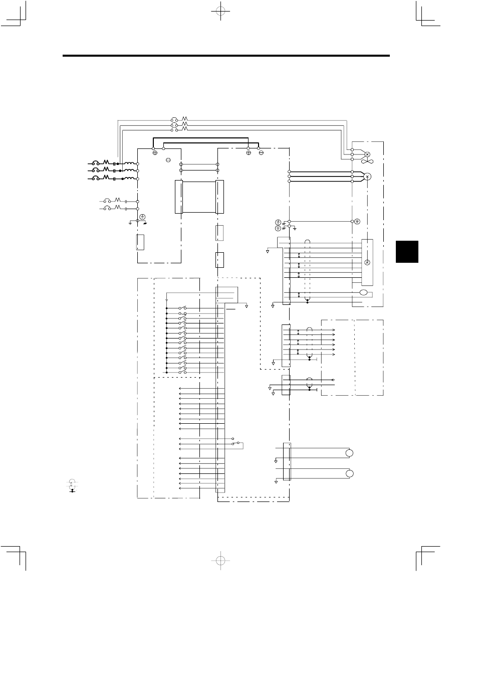
15.6.2 Speed Control Operation Combined with NC
This is the most popular operation using a main axis drive for a machine-tool. Sequence input signals such
as forward rotation and reverse rotation, and output signals such as zero speed and speed matching, are
connected to the I/O Module in the sequencer, and the speed references are connected to the axis control
module in the CPU. A basic connection example is shown in Fig. 15.30.
3MCCB
Special busbar
R
S
T
1MCCB 1MC
L
P/
N/
VS−656MR5
R/L1
S/L2
T/L3
P1
N1
5CN
P1
N1
51CN
VS−626M5
1-phase
200 VAC
r
t
2MCCB
2MC
A1/r
A2/t
Not used
1CN
P/
N/
Flat cable
3CN
P1N1 power
supply cable
Not used
52CN
Motor
Cooling fan
U
V
IM
2CN
+5V
0V
4,5,6
1,2,3
THSA
THSB
SS
8
7
9
1
2
3
4
5
6
7
8
9
11
12
10
PG
TS
P
PA
:
PA
PB
:
PB
PLC
PLC
16
17
18
19
14
15
P
P
P
PAO
:
PAO
PBO
:
PBO
PLCO
:
PLCO
13
14
15
16
11
12
P
P
P
SS 17
1CN
TLL(INC)
SSC(SV)
19,20,21
22,23
24,25
EXTCOM0*
2
24VCOM
0VCOM
Output Module
6CN
6
7
8
9
10
11
12
RDY
FWD
REV
TLH
13
14
5
15
16
17
18
RST
CHW
DAS
PPI
ORT
LGR
MGR
33
34
35
ZSPD
36
37
38
39
40
42
TDET
TLE
ORG
ORE
CHWE
COM1
SDET
AGR
43
44
45
FLT
26
27
28
29
FC0
FC1
FC2
FC3
30 COM2
I/O Card
indicates shielded twisted-
pair cable.
*1
400-V class: 3-phase 400 VAC
*
2
EXTCOM0 on 6CN and EXTCOM
on 1CN are isolated internally.
*
3
Connection when sequence input
common is an external common.
3-phase
200 VAC*
1
41
46
FLTL
TALM
W
Z1
Z2
Z3
NC
External 24 V
power supply
Input Module
LM
SM Speedometer
Load meter
SCOM
0 V
SS
3
4
2
6CN
Control Axis
Module
NC
U/T1
V/T2
W/T3
6CN
SM 47
0V 48
LM 50
0V 49
Digital Opera-
tor (optional)
P
3-phase
200 VAC*
1
(Ground to 100 Ω
or less.)
(Ground to 100 Ω
or less.)
MCCB: Molded Case Circuit Breaker
MC:
Magnetic Contactor
L:
AC reactor
*
3
EMG
Fig 15.30 Operation Combined with NC
15