4 details on sequence output signals – Yaskawa Varispeed 626M5 User Manual
Page 88
4.4 Sequence Output Signals
4 -13
4.4.4 Details on Sequence Output Signals
This section provides information on each of sequence output signal. Pin numbers are given for indepen-
dent drive operation (M5A). Refer to the manual for the NC machine for sequence output signals and out-
put addresses.
J
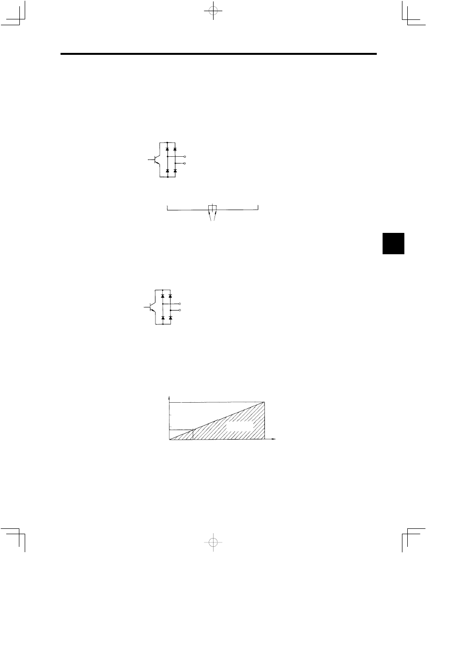
ZSPD (Zero-speed Signal)
Connector number: 6CN
Pin numbers:
33
42
D
The ZPSD signal will turn ON when the motor speed drops to the set speed or less. Once the ZPSD
signal turns ON, it will be kept on hold for 50 ms.
Reverse
Forward
Zero-speed detection level (C1-19)
6000 min
−1
6000 min
−1
[ZSPD] ON
D
The C1-19 (ZS
LVL
) can be set to a zero-speed detection level between 3 and 60 min
−1
.
D
The ZSPD signal is output regardless of the status of the FWD or REV output. Therefore, the ZSPD
signal can be used as an interlock signal for hazard prevention.
J
AGR (Speed Agree Signal)
Connector number: 6CN
Pin numbers:
34
42
D
The AGR signal will turn ON when the motor speed reaches the range set by the SCOM signal. The
AGR signal will not, however, turn ON while the gate is blocked or the motor winding is selected.
D
Once the AGR signal turns ON, it will be kept on hold for 50 ms.
D
The AGR signal can be used in response to the S reference for NC machines in program operation to
go to the next step.
D
The C1-20 (AGR
BD
) can be set to a speed agree signal detection width between ±10% and ±50%.
Operation Example of Speed Agree Signal
Speed reference vs. motor speed
AGR is OFF
100% speed reference
15%
4%
0
25%
C1−20 = 15%
AGR is ON
4