Yaskawa Varispeed 626M5 User Manual
Page 191
12.3 Inverter Faults
12 - 7
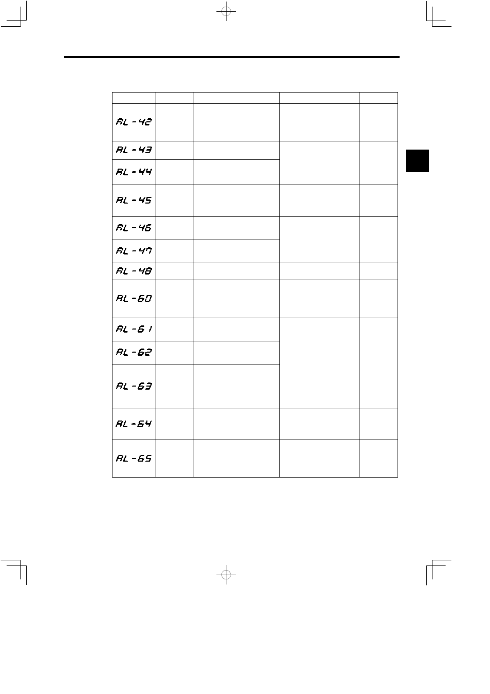
Table 12.2
Inverter Faults (continued)
Fault No.
Name
Contents
Corrective Actions
Error Code
Motor therm-
istor discon-
nection
Motor temperature detection therm-
istor was disconnected.
S
Check the motor thermistor sig-
nal wiring.
S
Check the motor ambient tem-
perature. (Raise the temperature
to above −10°C (14°F) or more.)
FfFF
Heatsink
overheat 1
Heatsink temperature exceeded up-
per limit (minor fault).
Check the ambient temperature
Heatsink
overheat 2
Heatsink temperature over upper
limit continued for one minute or
longer.
Check the ambient temperature
for effective cooling.
FfFF
Heatsink
thermistor
disconnection
Thermistor for heatsink temperature
detection was disconnected.
The ambient temperature is low
(−20°C (−4_F) or below).
S
Replace the unit.
S
Raise the ambient temperature
to above −20°C (−4°F).
FfFF
Control PCB
temperature
fault 1
Control PCB temperature exceeded
80°C (176°F) (minor fault).
Check the ambient temperature
FfFF
Control PCB
temperature
fault 2
Control PCB temperature exceeded
85°C (185°F).
Check the ambient temperature
for effective cooling.
FfFF
Internal cool-
ing fan fault
Inverter internal cooling fan is
stopped.
Replace the internal cooling fan.
FfFF
tuneup
incomplete
(Encoder
method
orientation)
Orientation command was input be-
fore tuning up (minor fault).
Perform orientation tuneup.
FffF
Phase-C sig-
nal detection
error
Phase-C signal could not be de-
tected during tuning up.
S
Check the wiring of encoder sig-
l li
Phase-C sig-
nal width er-
ror
Phase-C signal width exceeded 100
pulses.
g
g
nal lines.
S
Confirm that encoder signal
lines are separated from main
circuit or other power lines.
FffF
Fault of num-
ber of pulses
per rotation
(Encoder
method
orientation)
Number of pulses per rotation ex-
ceeded 4096 ±1 during tuning up.
circuit or other power lines.
S
Verify that motor and Inverter
are grounded.
S
Replace the Orientation Card.
S
Replace the encoder.
FffF
Position
detection sig-
nal cable
disconnection
Position detection encoder signal
cable was disconnected or con-
nected improperly.
S
Check the wiring of load shaft
encoder signal lines.
S
Replace the load shaft encoder.
S
Replace the Orientation Card.
FffF
INC signal er-
ror
(Encoder
method
orientation)
INC signal input timing error
(minor fault)
After carrying out absolute posi-
tioning, change circuit to com-
mand INC signal.
FffF
12