3 wiring main circuit terminals, 1 wires and suitable crimp connectors – Yaskawa Varispeed 626M5 User Manual
Page 47
3.3 Wiring Main Circuit Terminals
3 -7
3.3 Wiring Main Circuit Terminals
This section provides information on the specifications, functions, configuration, and wiring of main circuit
terminals.
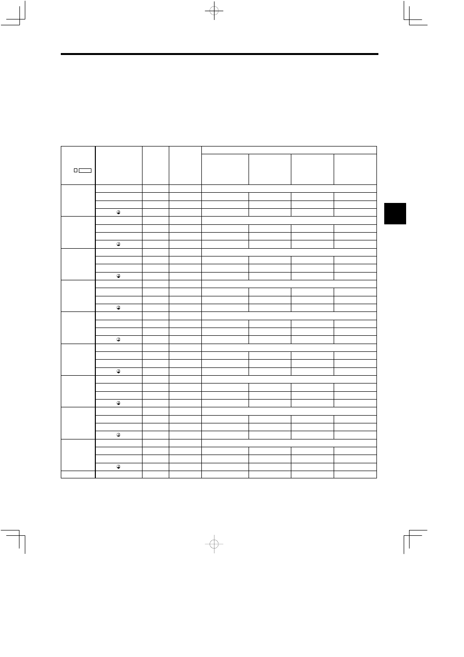
3.3.1 Wires and Suitable Crimp Connectors
Select wires or crimp connectors to be used from the following table.
Table 3.1
200 V Class Converter Power Cable Specifications
Wire Sizes
Model
CIMR-
MR5
Terminal Symbols
Terminal
Screw
Tightening
Torque
(N S m)
UL-approved
75°C (167°F)
Temperature-rated
Copper Wire
[AWG (mm
2
)]
600 V Vinyl-
sheath Insulated
Wire (IV, VV)
60°C (140°F)
(mm
2
)
600 V Cross-
linked Polyethy-
lene Wire (IC)
90°C (194°F)
(mm
2
)
600 V Rubber-
insulated Cab-
tyre Cable (CT)
60°C (140°F)
(mm
2
)
P/¨, N/©
M6
2.94
(*1)
23P7
R/L1, S/L2, T/L3
M5
2.35
14 (2.1)
2
2
2
23P7
A1/r, A2/t
M5
2.35
14 (2.1)
2
2
2
M4
1.2 − 2.0
10 (5.3)
2
2
2
P/¨, N/©
M6
2.94
(*1)
25P5
R/L1, S/L2, T/L3
M5
2.35
12 (3.3)
3.5
2
3.5
25P5
A1/r, A2/t
M5
2.35
14 (2.1)
2
2
2
M4
1.2 − 2.0
10 (5.3)
3.5
2
2
P/¨, N/©
M6
2.94
(*1)
27P5
R/L1, S/L2, T/L3
M5
2.35
10 (5.3)
3.5
2
3.5
27P5
A1/r, A2/t
M5
2.35
14 (2.1)
2
2
2
M4
1.2 − 2.0
10 (5.3)
3.5
2
3.5
P/¨, N/©
M6 × 2
2.94
(*1)
2011
R/L1, S/L2, T/L3
M6
3.4 − 4.9
8 (8.4)
8
3.5
8
2011
A1/r, A2/t
M4
1.2 − 2.0
14 (2.1)
2
2
2
M6
3.4 − 4.9
8 (8.4)
5.5
3.5
5.5
P/¨, N/©
M6 × 2
2.94
(*1)
2015
R/L1, S/L2, T/L3
M6
3.4 − 4.9
6 (13.3)
14
5.5
14
2015
A1/r, A2/t
M4
1.2 − 2.0
14 (2.1)
2
2
2
M6
3.4 − 4.9
8 (8.4)
8
5.5
5.5
P/¨, N/©
M6 × 2
2.94
(*1)
2018
R/L1, S/L2, T/L3
M6
3.4 − 4.9
4 (21.2)
22
8
22
2018
A1/r, A2/t
M4
1.2 − 2.0
14 (2.1)
2
2
2
M6
3.4 − 4.9
6 (13.3)
8
5.5
8
P/¨, N/©
M6 × 2
2.94
(*1)
2022
R/L1, S/L2, T/L3
M6
3.4 − 4.9
4 (21.2)
22
14
22
2022
A1/r, A2/t
M4
1.2 − 2.0
14 (2.1)
2
2
2
M6
3.4 − 4.9
6 (13.3)
14
8
8
P/¨, N/©
M6 × 2
2.94
(*1)
2030
R/L1, S/L2, T/L3
M8
7.8 − 9.8
2 (33.6)
38
2.2
38
2030
A1/r, A2/t
M4
1.2 − 2.0
14 (2.1)
2
2
2
M8
7.8 − 9.8
6 (13.3)
14
8
14
P/¨, N/©
M6 × 4
2.94
(*1)
2037
R/L1, S/L2, T/L3
M10
14.7 − 19.6
1/0 (53.5)
50
30
60
2037
A1/r, A2/t
M4
1.2 − 2.0
14 (2.1)
2
2
2
M8
7.8 − 9.8
4 (21.2)
22
14
14
2011 to 2037 A11/r1, A21/t1 (*2)
M4
1.2 − 2.0
14 (2.1)
2
2
2
* 1. Connect using exclusive-use connection bus bar.
* 2. Provided for open chassis type with a minimum capacity of 11 kW. Not provided for external heatsink cooling type.
3