3 using a 12-bit digital speed reference – Yaskawa Varispeed 626M5 User Manual
Page 85
Control Signals
4 -10
4.3 Using a 12-bit Digital Speed Reference
This section provides information on using a 12-bit digital speed reference input (for stand-alone drive systems
M5A only).
J
D1 through D12 (12-bit Digital References 1 through 12)
Connector number: 1CN
Pin numbers: 19 through 30
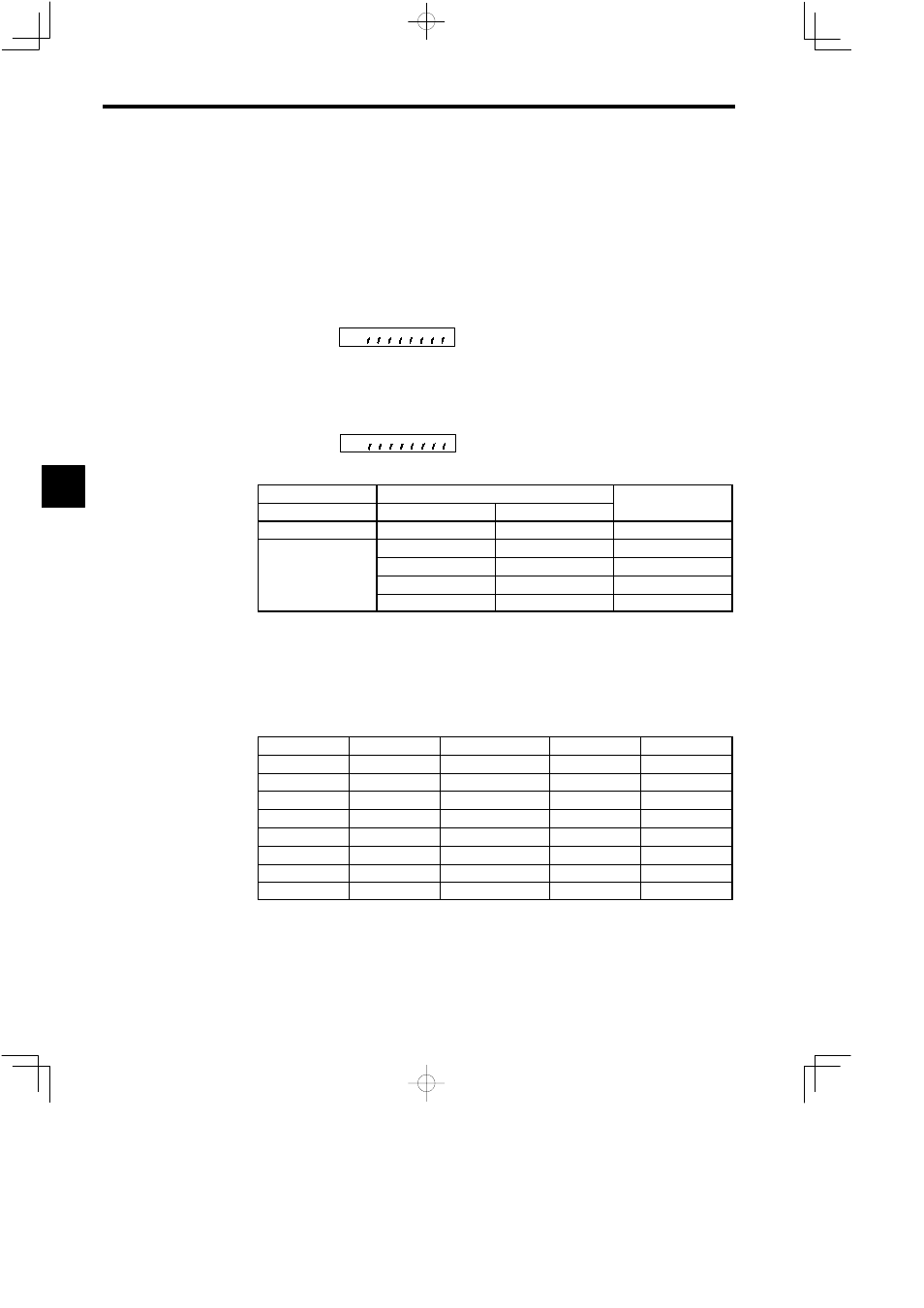
12-bit Digital Reference Signal Function Selection: 1CN-19 to 1CN-30 will be the 12-bit Digital Refer-
ence if bit 07 of the C1-36 selection signals (SEL1) is turned OFF.
Bit
7
C1−36
D
Bit 7 is used for internal speed or digital speed settings.
D
It is possible to select 12-bit binary, 2-digit BCD, 3-digit BCD, or internal speed setting for digital
speed references. Speed references are factory-set to 12-bit binary.
D
The setting method can be selected using bits 6 and 7 of selection signal C1-37 (SEL2).
Bit
7 6
C1−37
D
Selecting the Speed Setting
6CN-5, 19
C1-37 (SEL2)
Speed Selection
DAS
Bit 7
Bit 6
OFF
---
---
Analog speed
ON
OFF
OFF
2-digit BCD
OFF
ON
Binary
ON
OFF
3-digit BCD
ON
ON
Internal speed
D
The DAS signal can be switched only when the system is not in operation.
D
If the binary, BCD, or internal speed setting method is selected, the forward or reverse rotation of the
motor is selected with the external FWD or REV relay signal.
Internal Speed Setting
Number of speed settings: 8
Speed set value: Input into C1-41 through C1-48 the percentages based on the rated speed set for C1-26
(S100). Set range: 0.00 to 100.00
Control Constant
Signal
Name
1CN Input
Pin Number
C1-41
SPD1
Internal speed setting 1
D1
19
C1-42
SPD2
Internal speed setting 2
D2
20
C1-43
SPD3
Internal speed setting 3
D3
21
C1-44
SPD4
Internal speed setting 4
D4
22
C1-45
SPD5
Internal speed setting 5
D5
23
C1-46
SPD6
Internal speed setting 6
D6
24
C1-47
SPD7
Internal speed setting 7
D7
25
C1-48
SPD8
Internal speed setting 8
D8
26
D
If two or more speed selection signals (D1 through D8) are turned ON at the same time, the smaller
selection signal number will be enabled. (For example, if D2 and D5 are turned ON simultaneously,
D2 will be enabled.)
D
If all speed selection signals are OFF, the speed references are treated as 0.
D
No speed reference values in C1-41 through C1-48 can be changed while the system is in operation.
4