4 motor faults and corrective actions – Yaskawa Varispeed 626M5 User Manual
Page 197
12.4 Motor Faults and Corrective Actions
12 -13
12.4 Motor Faults and Corrective Actions
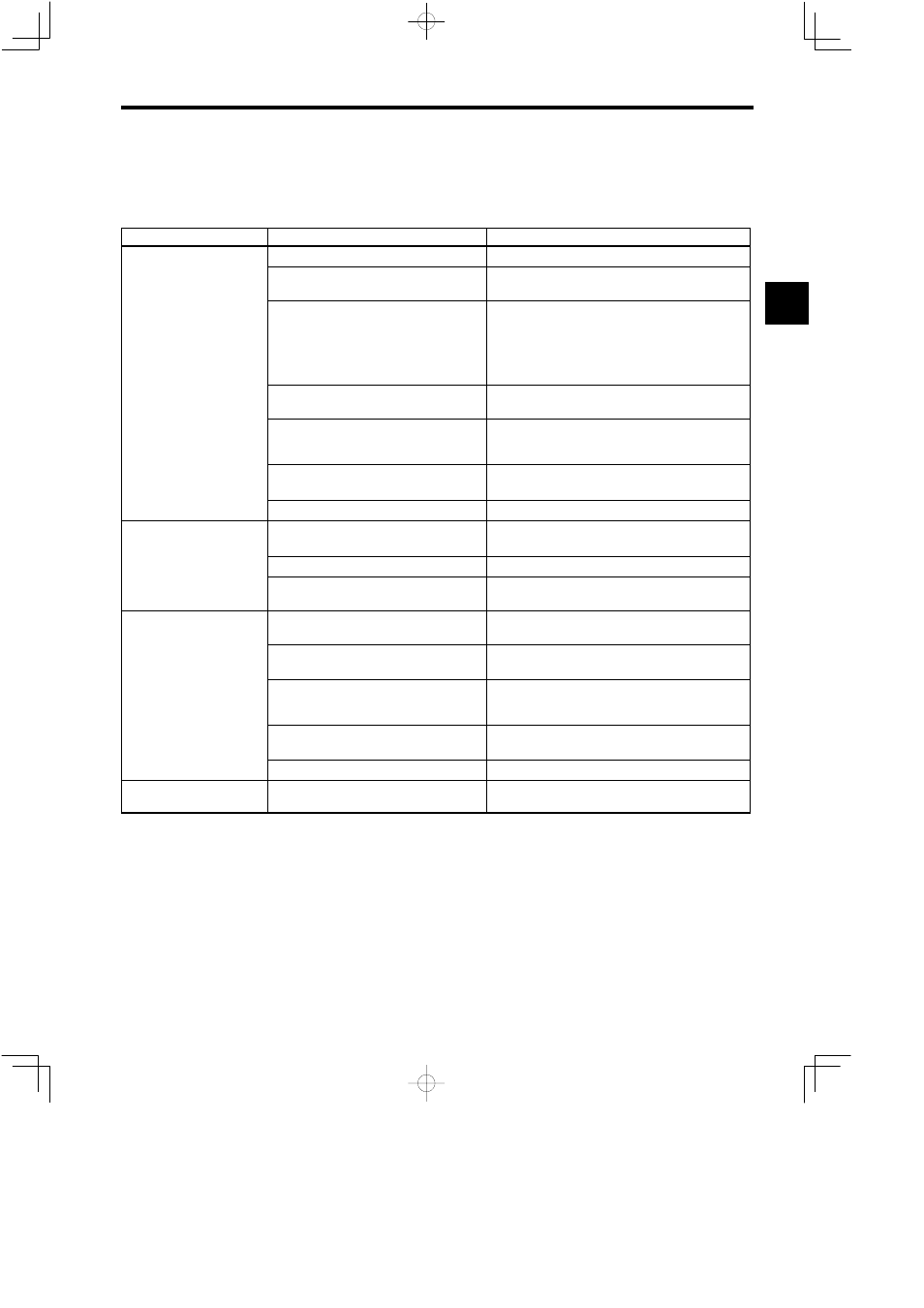
If any of the following faults occurs in the motor, check the cause and perform the relevant corrective actions.
Table 12.3
Motor Faults and Corrective Actions
Fault
Cause
Corrective Action
Protective function has been activated.
Check fault number and carry out appropriate steps.
Inverter output disconnection, improper connec-
tion
Check the wiring between Inverter and motor.
Motor does not rotate
Control signal does not function.
S
Check sequence input signal on operating status display
(U1-09) (RDY, EMG, FWD and REV).
S
Check if speed reference is input or not on operating status
display (U1-02).
S
Check if operating signal FWD or REV is input at least 15 ms
after RDY or EMG is input.
Motor does not rotate.
Torque limiting
Check whether external torque limit signals TLL or TLH is
input on operating status display (U1-09).
Motor winding wire disconnection
S
Check resistance between motor terminals (a circuit tester
necessary).
S
Replace the motor.
Motor fault (rotor and stator rub together, broken
bearing)
S
Check motor shaft rotation manually.
S
Replace the motor.
Control PCB fault
Replace the control PCB.
M t d
t t t
Power of Converter’s main circuit is not turn ON.
S
Turn ON power supply.
S
Check voltage.
Motor does not rotate.
(STOP LED blinks.)
Flat cable is not correctly connected.
Check that flat cable is correctly installed to connectors.
(STOP LED blinks.)
Timing of operating signal FWD, RED and EMG
is incorrect. (All signals input at the same time.)
Check if operating signal FWD or REV is input at least 15 ms
after RDY or EMG is input.
Inverter output disconnection, improper connec-
tion
Check the wiring between Inverter and motor.
Encoder signal line disconnection, improper con-
nection, loose connector (See note.)
Check the wiring of encoder signal line.
Motor rotates slowly or vi-
brates without rotation.
Motor encoder fault
S
Check for abnormal changes in motor speed on speedometer
or operating status display (U1-01).
S
Replace the encoder or the motor.
Torque limiting
Check whether external torque limit signals TLL or TLH is
input on operating status display (U1-09).
Control PCB fault
Replace the control PCB.
Motor rotates in
reverse direction.
Improper connection of Inverter output or motor
encoder signal line
Check the wiring according to the connection diagram.
12