1 procedure – Yaskawa Varispeed 626M5 User Manual
Page 110
Trial Operation
6 -4
6.1 Procedure
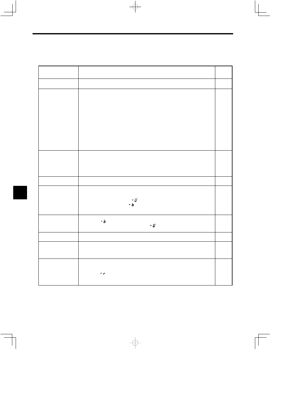
Perform trial operation according to the following flowchart.
Item
Details
Refer-
ence
Page
Installation and Mounting Install the Inverter and Converter according to the installation conditions.
S
Check that the installation conditions are satisfied.
1 -5
Wiring
Connect the power supply and peripheral devices.
S
Select peripheral devices that meet the specifications, and wire them firmly.
S
Be sure to check that the main circuit power supply input terminals (R/L1, S/L2, and T/L3) and control
power supply input terminals (A1/r and A/2t) are wired firmly.
S
Check that the Motor output terminals (U/T1, V/T2, and W/T3) and the Motor are connected firmly.
S
Check that the ground terminal is connected firmly.
S
Check that the wiring between the Converter and Inverter (main circuit DC (P/+ and N/−), control power
supply (P1 and N1), and control signal (5CN and 51CN)) is connected firmly.
S
If using a Unit mounted inside of a panel (11 kW min.), check that the power supply terminals (A1j/rj
and A2j/rj) for the cooling fan are connected firmly.
S
Check that the control circuit signal and Control Unit are wired firmly and be sure that all control circuit
signals are OFF.
S
If using an Orientation Card, check that the Card is wired firmly.
S
If using a magnetic contactor for switching windings, check that the contactor is wired firmly.
2 -3
Check Power Supply
Voltage
Check that the power supply voltage is correct before turning ON the power supply.
S
Main circuit power supply voltage
200 V class: 3-phase 200 to 230 VAC, 50/60 Hz
400 V class: 3-phase 400 to 460 VAC, 50/60 Hz
S
Control power supply voltage
1-phase 200 to 230 V, 50/60 Hz
5 -5
Set YENET1200 Node
Address
If using an NC Drive (M5N), set the Inverter YENET1200 node address correctly using rotary switch
SW1.
5 -5
Turn ON Control Power
Supply
Turn ON the control power supply, and check that there are no abnormalities with the Inverter and
Converter.
S
If the 7-segment LED display is normal when the power supply is turned ON, it will read as follows:
Converter LED display: “
”
Inverter LED display: “
”
S
If an error occurs, details of the error will be displayed on the LED display (or on the Digital Operator
data display). Refer to Chapter 12 Troubleshooting, and perform the appropriate remedy.
5 -5
Turn ON Main Circuit
Power Supply
Turn ON the main circuit power supply, and check that the 7-segment LED display on the Converter
has changed to “
” .
S
If the Converter LED display continues to display “
”, the main circuit input voltage is too low, or
the phase has been interrupted. Check the input power supply voltage.
5 -5
Check Motor Cooling Fan When the main circuit power supply is turned ON, the Motor cooling fan will start to rotate. Check that
the direction of the Motor air flow is correct as shown in Fig 6.1.
5 -6
Check Motor Code
Check that the Motor code selection (C1-25) is set correctly. (Check the Motor model and Motor code
using the factory settings table enclosed with the Inverter.)
S
If changing the Motor code (C1-25) set value, be sure to turn OFF the control power supply for three
seconds and then turn it ON again to enable the changed settings.
5 -11
Perform Trial Operation
Send the RUN signal to start trial operation. (If using a Digital Operator for the trial operation, refer to
5.3.5 Digital Operator Operation Mode.)
S
When the RUN signal is sent, check that the 7-segment LED display on the Inverter and Converter
changes to “
”.
S
Check that the direction of Motor rotation is correct.
S
Check that there is no abnormal vibration or noise coming from the Motor.
5 -5
6