2 acceleration/deceleration capacity – Yaskawa Varispeed 626M5 User Manual
Page 287
15.3 Determining Drive Capacity
15 -15
15.3.2 Acceleration/deceleration Capacity
When stopping machinery operation, the acceleration method can be selected from rapid acceleration/de-
celeration to smooth acceleration/deceleration, depending on the application. A comparison of these ac-
celeration methods is shown in Table 15.4. Calculate the acceleration/deceleration capacity using the se-
verest current-limiting acceleration according to capacity. The formula for calculating the drive capacity
required from the acceleration time t (s) is shown below.
D
Required drive capacity of the fixed torque characteristics range (0 ≦N
M
≦ N
B
)
P
M
=
2 π
60
2
J
M
N
M
2
1000 t
(kW)
D
Required drive capacity of the fixed torque characteristics + the fixed output characteristics range
(0 ≦N
M
≦ N
MAX
)
P
M
=
2 π
60
2
J
M
(N
M
2
+ N
B
2
)
2000 t
(kW)
J
M
:
Motor axis conversion inertial moment (kg
⋅
m
2
)
P
M
:
Basic low-speed motor output (kW)
N
M
:
Operation speed (min
−1
)
N
B
:
Basic low speed (min
−1
)
N
MAX
:
Maximum speed (min
−1
)
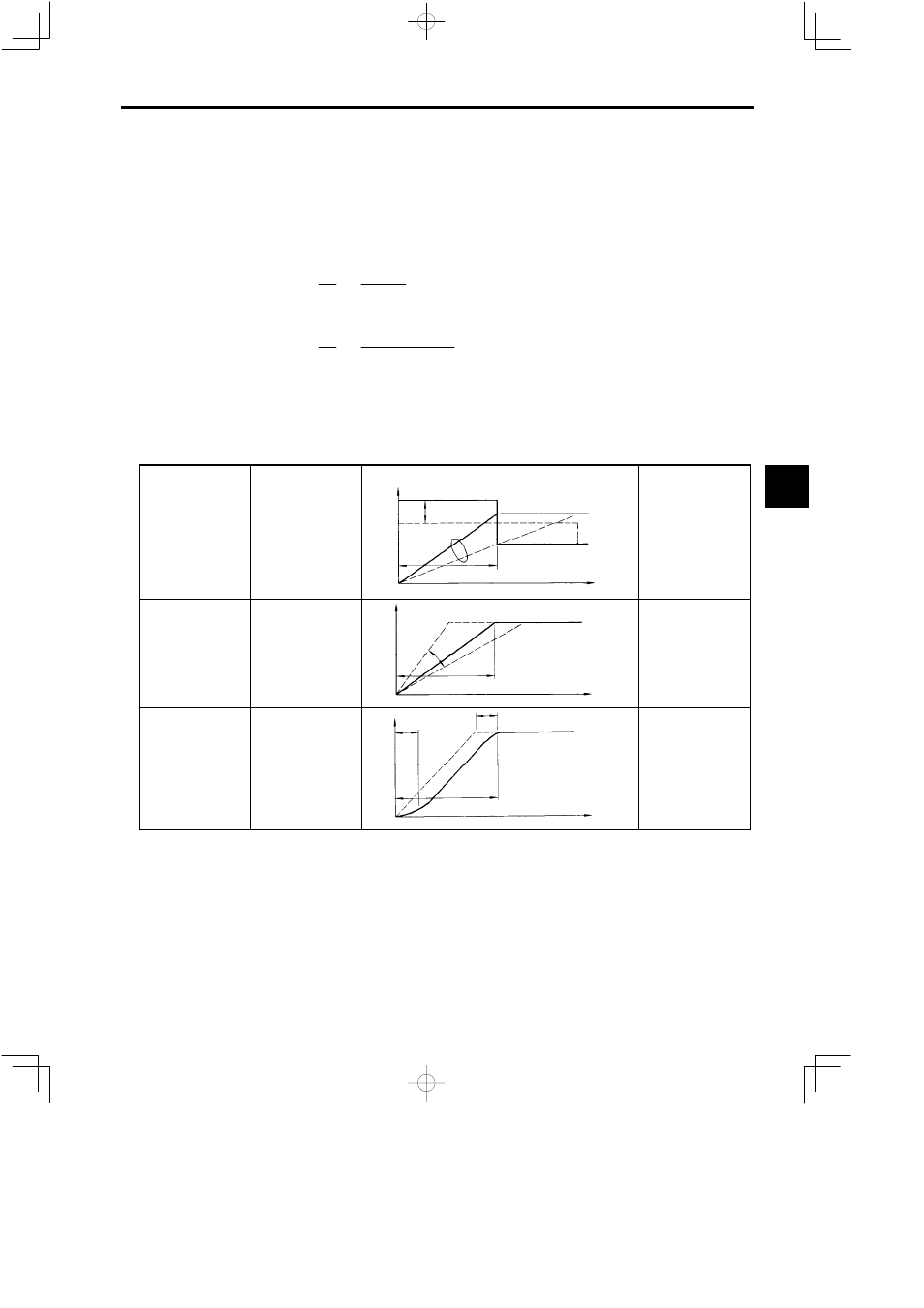
Table 15.4 Acceleration Formulas
Acceleration Method
Control Method
Explanatory Diagram
Remarks
Current-limited Accel-
eration
This method suppresses
the current during accel-
eration to a fixed value
to protect the drive unit
and machinery.
Current
and speed
Current limit
Adjustable range
Speed
ta
Time
0
Fixes the torque gener-
ated by the motor during
acceleration.
Time-limited Accelera-
tion
This method suppresses
the acceleration rate so
that there is linear accel-
eration change over
time, against rapid
speed reference
changes.
Speed
ta
Time
0
Adjustable
range
Fixes the acceleration
torque.
S-curve Acceleration
This method further
suppresses torque over
the above method, to
perform smooth accel-
eration.
Speed
ta
Time
0
Adjustable
range
Speed
Suppresses the rate of
variation in the torque at
the start and end points
during acceleration.
An example of calculations based on standard drive and machinery specifications is shown below. With
actual machinery, the calculated values may vary slightly due to mechanical loss, fluctuations in the power
supply voltage, and machine noise and motor magnetic field noise countermeasures.
15