Configuration of the write-in data – Yaskawa MP900 Series Machine Controller New Ladder Editor User Manual
Page 229
2 Standard System Function
2.3.1 Inverter Constant Write Function (ICNS-WR)
2-36
Note: In the case of an inverter response error, the error codes from the
inverter are indicated in bit 0 to bit 7.
01H(1) : function code error
02H(2) : reference No. error
03H(3) : write-in count error
21H(33) : write-in data upper/lower limit error
22H(34) : write-in error (during running, during UV)
Numbers in ( ) are of decimal expressions.
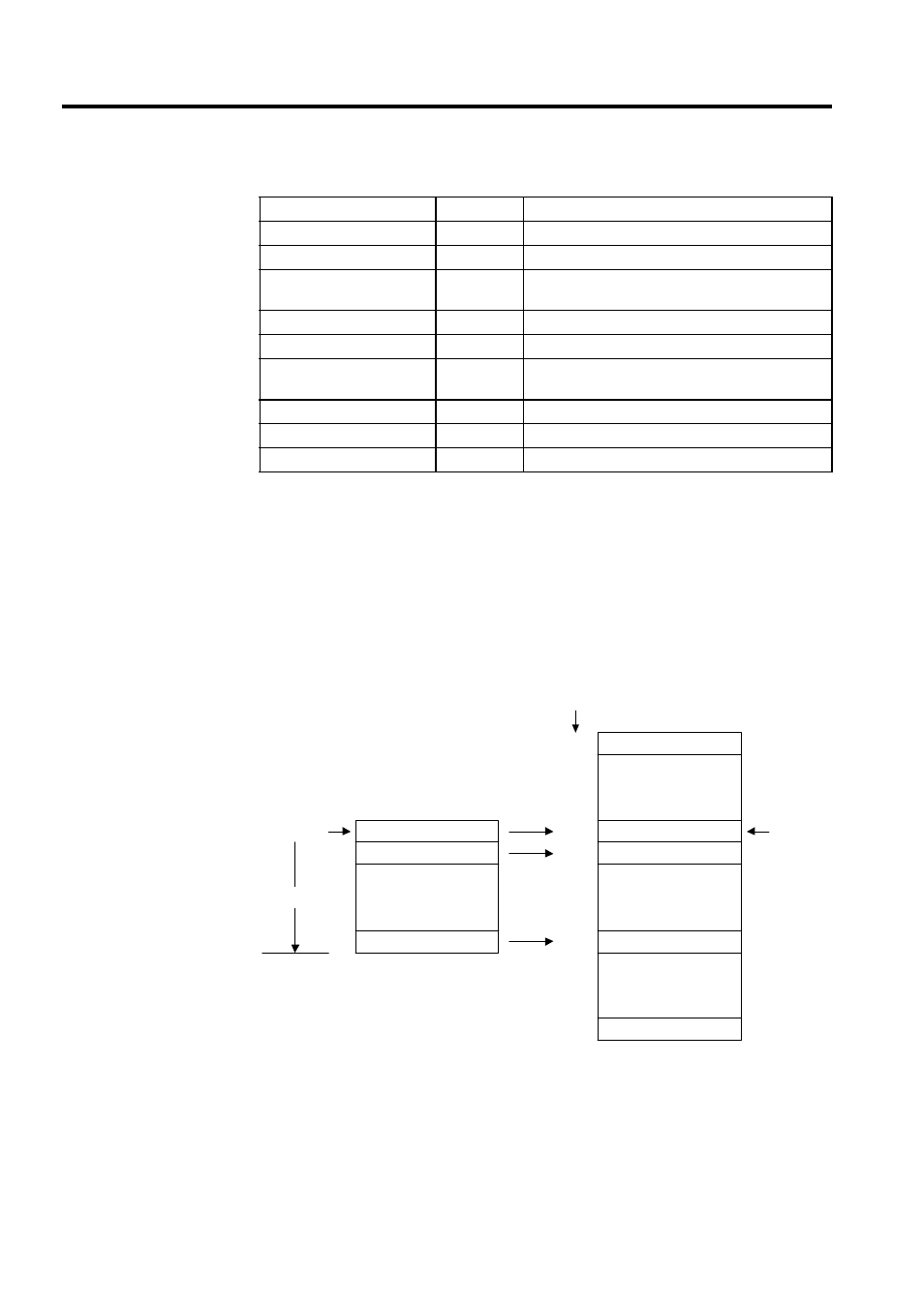
Configuration of the Write-in Data
Table 2.15 Configuration of Inverter Constant Write Execution Status (STATUS)
Name
Bit No.
Remarks
System reserved
bit0 to bit7
Execution sequence error
bit8
The function will not be executed.
Transmission parameter
error
bit9
The function will not be executed.
Designated type error
bit10
The function will not be executed.
Designated No. error
bit11
The function will not be executed.
Error in number (amount)
of the designated data
bit12
The function will not be executed.
Transmission error
bit13
The function will not be executed.
Inverter response error
bit14
The function will not be executed.
Address input error
bit15
The function will not be executed.
bn-01
ASR integration time
PG dividing ratio
bn-05
bn-14
Cns-No
Cns-Size
Constant data 10
Constant data 2
Constant data 1
User Register
ASR proportional gain
AO optional output gain
Acceleration time 1
Inverter Constants
bn-25
bn-06
Cns-Typ
Dat-Adr
•
•
•
•
•
•
•
•
•
•
•
•
•
•
•
•