Format – Yaskawa MP900 Series Machine Controller New Ladder Editor User Manual
Page 174
1 Ladder Program Instructions
1.7.13 PULSE WIDTH MODULATION Instruction (PWM)
1-164
* Relay I/O Bit Assignment
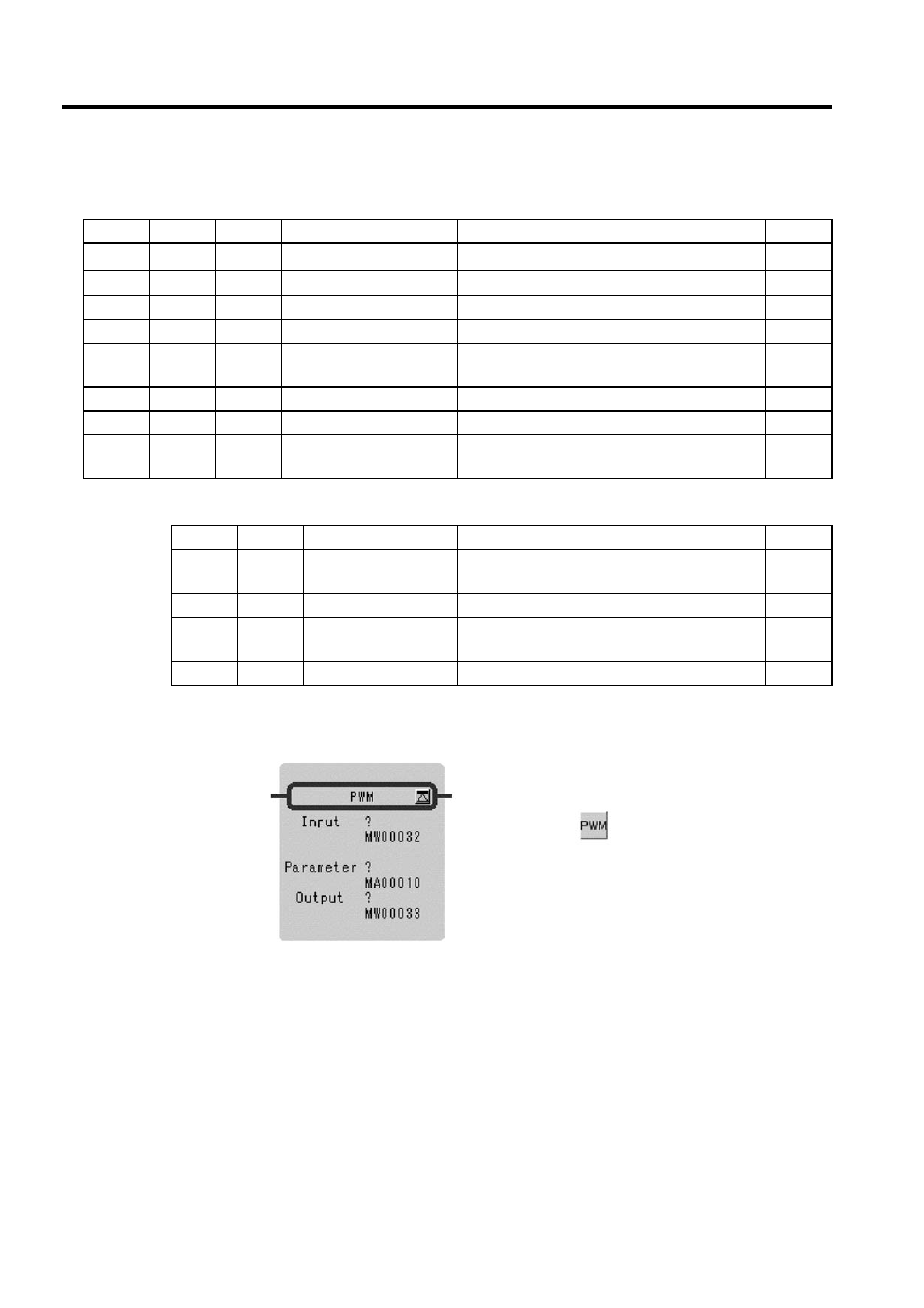
Format
Table 1.30 Integer Type PWM Instruction Parameters
ADR
Type
Symbol
Name
Specifications
I/O
0
W
RLY
Relay I/O
Relay input, relay output
∗
IN/OUT
1
W
PWMT
PWM cycle
PWM cycle (1 ms) (1 to 32767 ms)
IN
2
W
ONCNT
ON output set timer
Set timer for ON output (1 ms)
OUT
3
W
CVON
ON output counting timer
Counting timer for ON output (1 ms)
OUT
4
W
CVON
REM
ON output counting timer
remainder
ON output counting timer remainder (0.1 ms)
OUT
5
W
OFFCNT OFF output set timer
Set timer for OFF output (1 ms)
OUT
6
W
CVOFF
OFF output counting timer
Counting timer for OFF output (1 ms)
OUT
7
W
CVOFF
REM
OFF output counting timer
remainder
OFF output counting timer remainder (0.1 ms)
OUT
BIT
Symbol
Name
Specifications
I/O
0
PWM
RST
PWM reset
"ON" is input when PWM is reset
IN
2 to 7
−
(Reserved)
Reserved relay for input
IN
8
PWM
OUT
PWM output
PWM is output (2 value output: ON
= 1, OFF = 0)
OUT
9 to F
−
(Reserved)
Reserved relay for output
OUT
Symbol: PWM
Full Name: Pulse Width Modulation
Category: DDC
Icon: