Yaskawa MP900 Series Machine Controller New Ladder Editor User Manual
Page 167
1.7 DDC Instructions
1-157
1
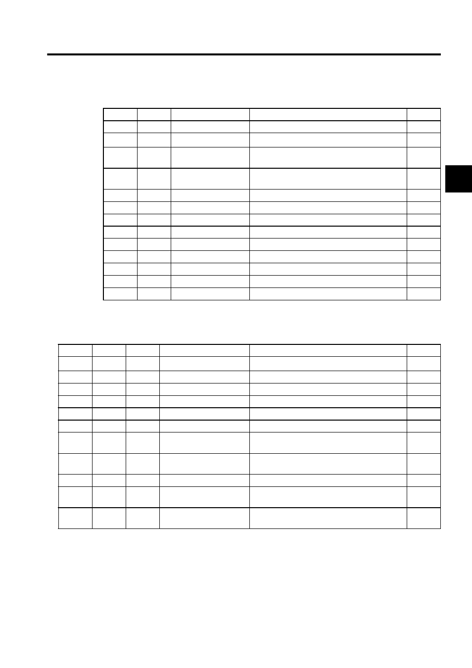
* Relay I/O Bit Assignment
* When the quick stop (QS) is "OFF", the quick stop time is used for the acceleration/deceleration
time
.
BIT
Symbol
Name
Specifications
I/O
0
RN
Line is running
"ON" is input while the line is running.
IN
1
QS
Quick stop
"OFF" is input upon quick stop
∗
IN
2
DVDTF
Non-execution of
DVDT1 operation
Input of "OFF" into non-execution of DVDT1 opera-
tion.
IN
3
DVDTS
DVDT1 operation se-
lection
Selection DVDT1 operation method
IN
4 to 7
−
(Reserved)
Reserved relay for input
IN
8
ARY
In acceleration
"ON" is output during acceleration.
OUT
9
BRY
In deceleration
"ON" is output during deceleration.
OUT
A
LSP
Zero speed
"ON" is output upon attainment of a speed of 0.
OUT
B
EQU
Coincidence
"ON" is output when input value
= output value.
OUT
C
EQU
(Reserved)
Reserved relay for output
OUT
D
CCF
Work relay
System internal work relay
OUT
E
BBF
Work relay
System internal work relay
OUT
F
AAF
Work relay
System internal work relay
OUT
Table 1.29 Real Type SLAU Instruction Parameters
ADR
Type
Symbol
Name
Specifications
I/O
0
W
RLY
Relay I/O
Relay input, relay output
∗
IN/OUT
1
W
−
(Reserved)
Reserved register
−
2
F
LV
100% input level
Scale of the 100% input
IN
4
F
AT
Acceleration time
Time for acceleration from 0% to 100% (s)
IN
6
F
BT
Deceleration time
Time for deceleration from 100% to 0% (s)
IN
8
F
QT
Quick stop time
Time for quick stop from 100% to 0% (s)
IN
10
F
AAT
S-curve acceleration time
Time spent in the S-curve area during acceleration
(s)
IN
12
F
BBT
S-curve deceleration time
Time spent in the S-curve area during deceleration
(s)
IN
14
F
V
Current speed
SLAU output (also output to the F register)
OUT
16
F
DVDT
Current acceleration/de-
celeration
Scaled with the normal acceleration rate being set.
OUT
18
F
ABMD
Speed increase upon hold-
ing
Amount of change in speed after hold instruction
until stabilization.
OUT