10 .1 1 pr ogr amming examples – HEIDENHAIN TNC 426 (280 476) User Manual
Page 420
HEIDENHAIN TNC 426, TNC 430
393
1
0
.1
1 Pr
ogr
amming Examples
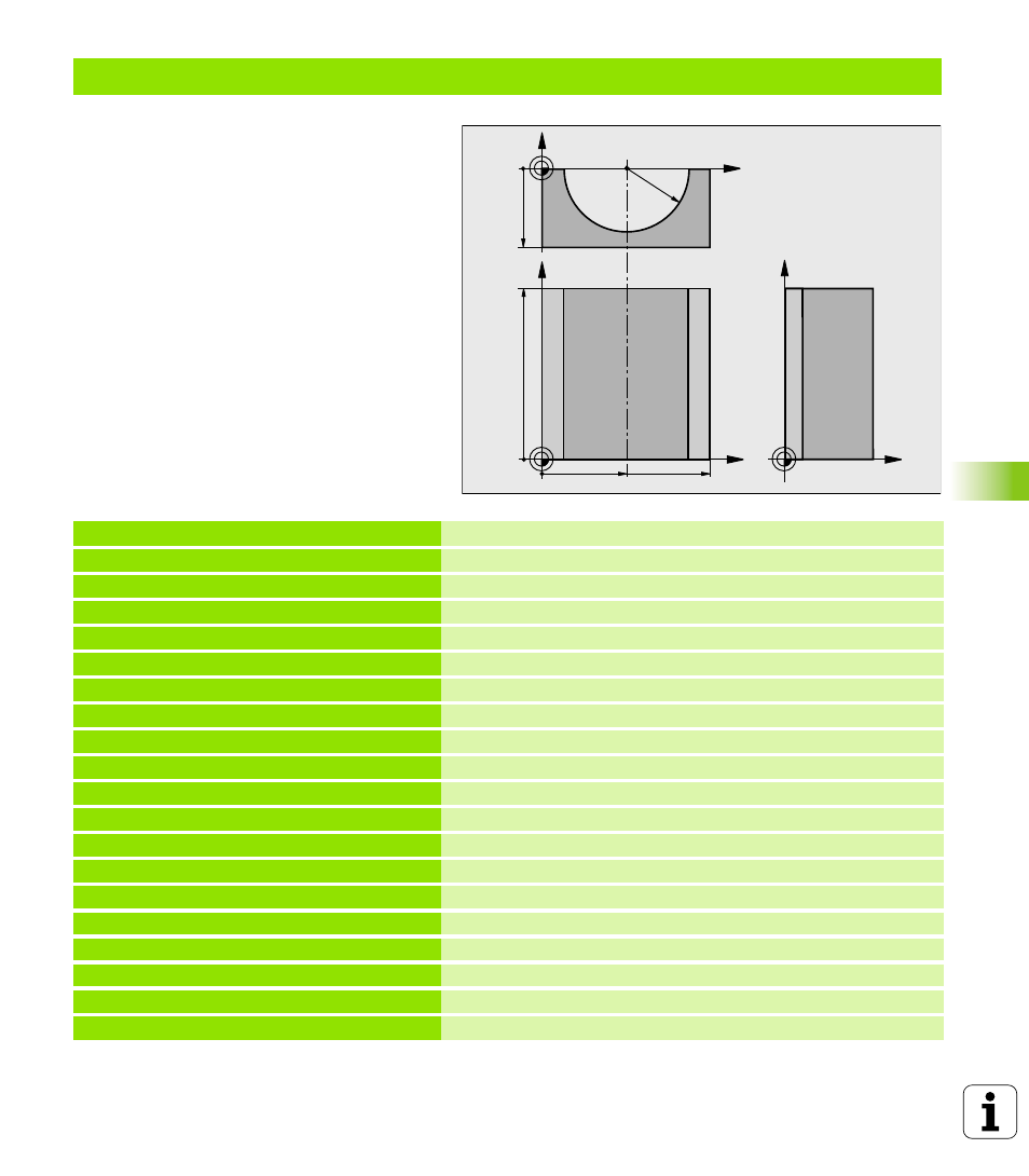
Example: Concave cylinder machined with spherical cutter
Program sequence
n
Program functions only with a spherical cutter.
The tool length refers to the sphere center.
n
The contour of the cylinder is approximated by
many short line segments (defined in Q13). The
more line segments you define, the smoother
the curve becomes.
n
The cylinder is milled in longitudinal cuts (here:
parallel to the Y axis).
n
The machining direction can be altered by
changing the entries for the starting and end
angles in space:
Clockwise machining direction:
starting angle > end angle
Counterclockwise machining direction:
starting angle < end angle
n
The tool radius is compensated automatically.
0 BEGIN PGM CYLIN MM
1 FN 0: Q1 = +50
Center in X axis
2 FN 0: Q2 = +0
Center in Y axis
3 FN 0: Q3 = +0
Center in Z axis
4 FN 0: Q4 = +90
Starting angle in space (Z/X plane)
5 FN 0: Q5 = +270
End angle in space (Z/X plane)
6 FN 0: Q6 = +40
Radius of the cylinder
7 FN 0: Q7 = +100
Length of the cylinder
8 FN 0: Q8 = +0
Rotational position in the X/Y plane
9 FN 0: Q10 = +5
Allowance for cylinder radius
10 FN 0: Q11 = +250
Feed rate for plunging
11 FN 0: Q12 = +400
Feed rate for milling
12 FN 0: Q13 = +90
Number of cuts
13 BLK FORM 0.1 Z X+0 Y+0 Z-50
Define the workpiece blank
14 BLK FORM 0.2 X+100 Y+100 Z+0
15 TOOL DEF 1 L+0 R+3
Define the tool
16 TOOL CALL 1 Z S4000
Tool call
17 L Z+250 R0 F MAX
Retract the tool
18 CALL LBL 10
Call machining operation
19 FN 0: Q10 = +0
Reset allowance
X
Y
50
100
100
Z
Y
X
Z
-50
R40