2 checking the plc inputs and outputs – HEIDENHAIN TNC 306 Service Manual User Manual
Page 84
SERVICE MANUAL TNC 306/360
Page 77
HEIDENHAIN Service
17.2 Checking the PLC Inputs and Outputs
Three test units are available to check the inputs and outputs of the PLC:
- PLC test unit for:
X21 (PLC output at the logic unit)
X22 (PLC input at the logic unit)
- Measuring adaptor1) for: X27 (connection of the machine operating panel
at the logic unit)
- PL-test adaptor for:
X1 to X3 (PLC outputs at the PL 400)
X4 to X9 (PLC inputs at the PL 400)
With the PLC test unit all inputs and outputs of a connector are displayed simultaneously.
Moreover, the voltages can be measured.
1) If no PLC test unit is available, the measuring adaptor can be used for all PLC inputs and
outputs of the LE.
17.2.1 PLC Inputs
The inputs are tested as follows:
a) Connect the test unit between LE and PLC or between PL and PLC.
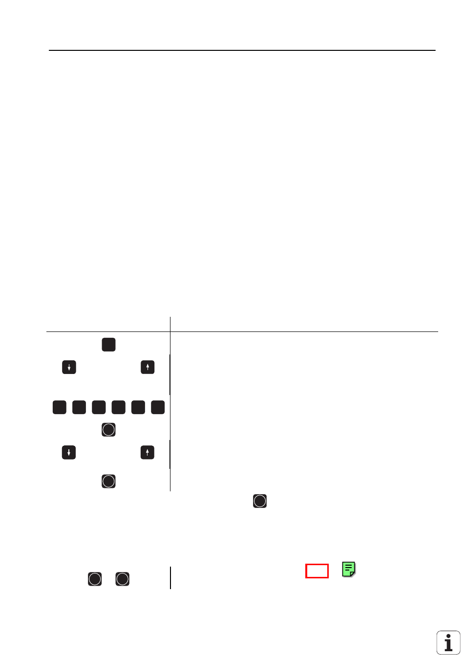
b) Set the TNC as follows:
Press key
Function
MOD
select auxiliary mode "MOD"
or
press key repeatedly, until the dialog CODE NUMBER= is
displayed
8
0
7
6
6
7
enter code number
ENT
activate PLC mode
or
select item TABLE I/O/C/T/M
ENT
activate item
Now, a table is displayed on the screen. Press
ENT
until the table INPUT is displayed. The
logic states of the inputs are displayed on the screen. The states of the screen display must
correspond to those of the test unit. If there is a difference, measure the voltage level (see
section 17.1) of this input at the TEST UNIT. If the input voltage is correct, the input board
is probably defective (I0 to I31 and I128 to I151 PLC-board I64 to I126 I/O-board PL 400).
ENT
ENT
exit PLC mode
*
Note:
Always switch off the main switch, when engaging or disengaging any
connectors.