1 checking the analog output: measurement setup – HEIDENHAIN TNC 306 Service Manual User Manual
Page 79
SERVICE MANUAL TNC 306/360
Page 72
HEIDENHAIN Service
When the override potentiometer is turned to the right, the control outputs an analog
voltage which is increased proportionally to the servo lag up to 10V max. The control is
operating correctly if a voltage of 10V
±
0.1V can be measured at the TEST ADAPTOR with
the multimeter. If no voltage can be measured, switch off the main switch, disconnect the
connector X8 from the LE, disconnect the nominal value line from the servo amplifier and
test for short-circuit. If the nomial value line is in order, connect the connector X8 to the LE
again (leave the nominal value line of the servo amplifier disconnected), switch on the main
switch and repeat the measurement with reference mark traverse. If an analog voltage can
be measured now, the control is operating correctly. If no voltage can be measured, the
analog output of the LE is probably defective.
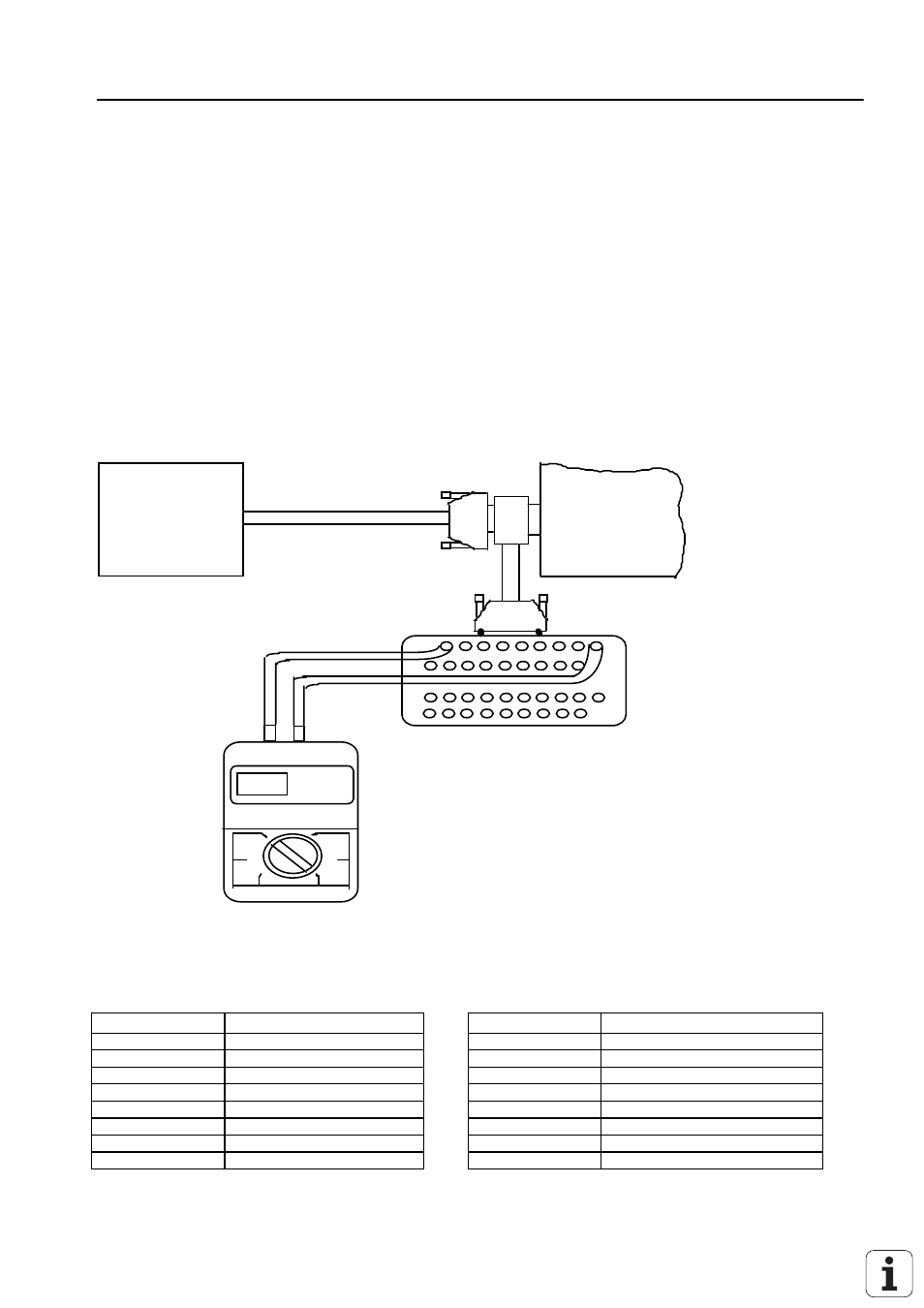
16.2.1 Checking the Analog Output: Measurement Setup
servo
amplifier
logic unit
multimeter
X8
5.15 V
measuring
adaptor
X8 Nominal Value Output 1 2, 3, 4, S (TNC 360)
1, 2, 3, 4 (TNC 306)
Flange socket with female insert (15-pin)
Pin No.
Signal Designation
Pin No.
Signal Designation
1
±
10V analog output 1.- axis
9
0V analog output 1. axis
2
analolg input (0...4.999V) max.
10
0V analog input
3
±
10V analog output 2. axis
11
0V analog output 2. axis
4
±
10V analog output 5. axis
13
0V analog output 3. axis
5
±
10V analog output 3. axis
14
0V analog output 4. axis
6
0V analog output 5. axis
15
0V analog output S-axis
7
±
10V analog output 4-. axis
12
not assigned
8
±
10V analog output S-axis
housing
external shield = housing
Attention:
Always switch off the main switch when engaging or disengaging any connectors.