Analog outputs, 1 specifications, 2 checking the analog output – HEIDENHAIN TNC 306 Service Manual User Manual
Page 78
SERVICE MANUAL TNC 306/360
Page 71
HEIDENHAIN Service
16. Analog Outputs
16.1 Specifications
5 outputs 1, 2, 3, 4 and S (TNC 360)
4 outputs 1, 2, 3, 4 (TNC 306)
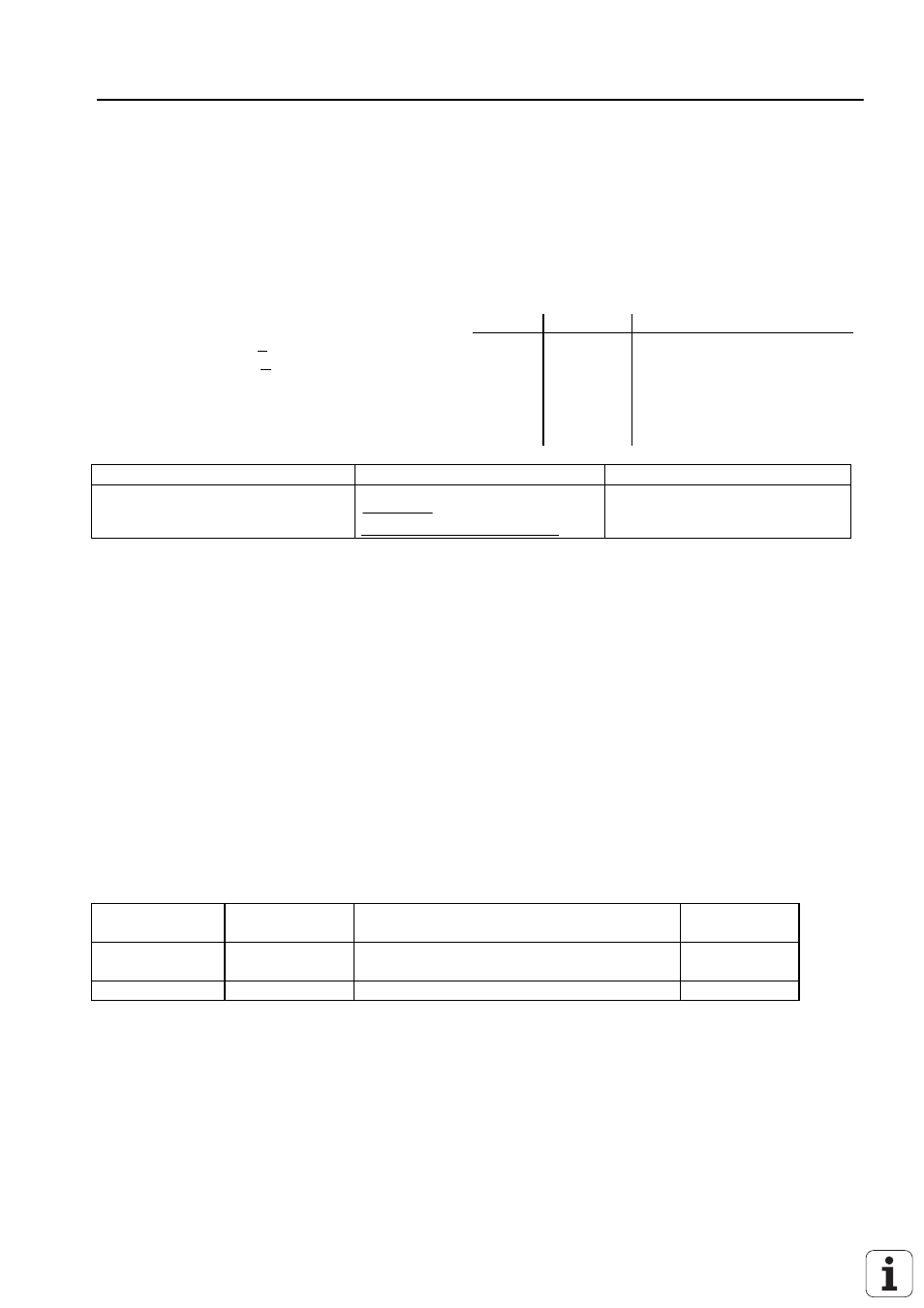
Machine parameters for the analog outputs
Axis
MP
Load capacity RLmin > 5 k
Ω
CLmax < 2 nF
Voltage range
Uamax = 10V
±
100 mV
Uamin = 0V
±
3 mV
X
Y
Z
IV
0 = output 1
1 = output 2
2 = output3
3 = output 4
(4 = output 5)
5 = output S (only TNC 360)
Resolution
14 bits = 16 384 steps
smallest step
10
16384
0 610
V
mV
=
.
16.2 Checking the Analog Output
Proportionally to the traversing speed, the control generates an analog voltage of 0V to 9V (depending
on MP 1050.X). The easiest way to determine this voltage is to connect the TEST ADAPTOR directly to
the LOGIC UNIT or to the connecting terminals of the servo-amplifier and to measure with a multimeter.
If however, the axis does not move due to a defect, and if you want to test whether the error is inside or
outside the control, the following steps are recommended:
- Switch off main switch of the machine tool
- Connect the TEST ADAPTOR to the connector X8 (nominal value output) of the LE and connect a
multimeter to the TEST ADAPTOR sockets for the defective axis.
If no TEST ADAPTOR is available, connect a multimeter directly to the nominal value input of the servo-
amplifier.
- Switch on the main switch and the control voltage.
- Switch the position display to "Servo Lag".
- Check or adjust the following machine parameters (If you alter the machine parameters, note down the
original entry values and enter them again after finishing the test.)
Parameter No. Entry value
Function
Original
entry value
100 (mm)
servo lag monitoring
EMERGENCY STOP
9.99 (V)
movement monitoring
- Traverse those reference points that need to be traversed before those of the defective axis.
- Turn the override potentiometer of the KEYBOARD UNIT completely to the left and start reference point
traverse for the defective axis.
- Check the axis enable for the defective axis at the servo amplifier.
- Check the screen display
* (control ready for operation) must be switched on, the "F" of the feed display must be lit normally (if the
display is inverse the feed enable is missing) and the symbol for "axis not in the position loop", e.g. X
,
should not follow the position display.
- Turn the override potentiometer slowly to the right and turn it back left before the servo lag display reaches