Rear panel view, Sda-00 model rear panel view, Chapter 1 product description – Grass Valley K2 Media Client System Guide v.3.3 User Manual
Page 28
28
K2 Media Client System Guide
June 9, 2009
Chapter 1 Product Description
Rear panel view
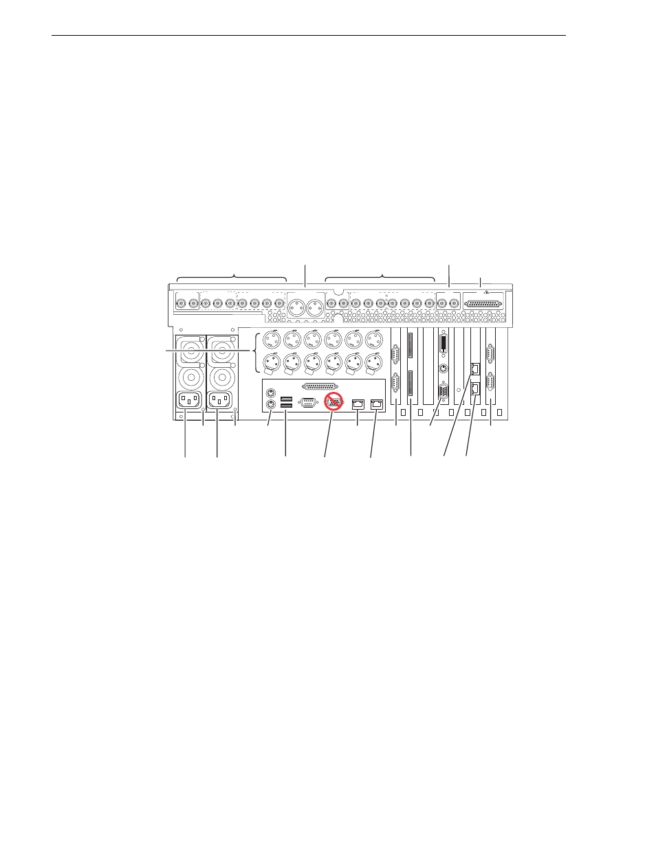
The following drawings identify the rear panel connectors and components. Some
cards are in different locations for the different models.
NOTE: All models can have an optional Fibre Channel board. Models with the
Fibre Channel option do not have the GigE port 3/port 4 board.
SDA-00 model rear panel view
Refer to
“RS-422 connections” on page 178
to connect and configure for RS-422
control.
Push
Push
Push
Push
Push
Push
P1 CH1
Analog
Audio
Analog
Audio
P1 CH2
P2 LTC
P2 CH1
P2 CH2
R2 CH2
R2 CH1
R2 LTC
R1 CH1
R1 CH2
R1 LTC
P1 LTC
OUT
IN
R1 IN
R1 IN
CH 1/2
CH 1/2
CH 3/4
CH 3/4
P1 OUT
P1 OUT 1
L
R
P1 OUT 2
R2 IN
R2 IN
CH 1/2
CH 1/2
CH 3/4
CH 3/4
P2 OUT
P2 OUT 1 P2 OUT 2
CMPST R1 & P1
SDI R1 & P1
AES/EBU R1 & P1
CMPST R2 & P2
SDI R2 & P2
AES/EBU R2 & P2
REF
COMPOSITE LOOP
THRU
R2 IN
P2 OUT
R1 IN
P1 OUT
AUD MON OUT
GPI
!
Channels R1 & P1 In/Out
(Loop-Thru)
Channels R2 & P2 In/Out
Reference
In
Audio Monitor
Out
GPI
Power
Good
LED
Power
Good
LED
Keyboard
/Mouse
USB
VGA
Display
GigE
Port 1
RS-422*
RS-422*
Do Not
Use**
Do Not
Use
GigE
Port 3
GigE
Port 4
GigE
Port 2
Power
Cord
LTC and
Analog Audio
In/Out
Power
Cord
Not present on some external
storage models.
**
RS-422 configuration varies. Some
systems have one RS-422 board.
*