Dtr alarm control and status table, Services screen, Dtr alarm control and status table -22 – Verilink WANsuite 7105 (34-00316.C) Product Manual User Manual
Page 54: Services screen -22
3-22
W A N s u i t e 7 1 0 5
Parity
Sets the parity bit.
Values: None, Odd, Even
Default: None
Stop Bit
Selects the number of bits required to end the character.
Values: 1, 2
Default: 1
Current Pin Status
Shows the status of the DTE Supervisory port pins.
DTR Alarm Control and Status Table
In addition to the configurable fields, the Supervisory screen displays a table
that lets you set the Data Terminal Ready (DTR) Alarm Control parameters
and view the current DTR Alarm Status.
Choices for DTR Alarm Control are “Enable” and “Disable”; the default
setting is “Disable.” Setting DTR Alarm Control to “Enable” allows the unit
to generate an alarm on loss of DTR, which occurs when the Serial port
detects that the DTR signal is low. The DTR Status field indicates the current
state of the DTR alarm.
Services Screen
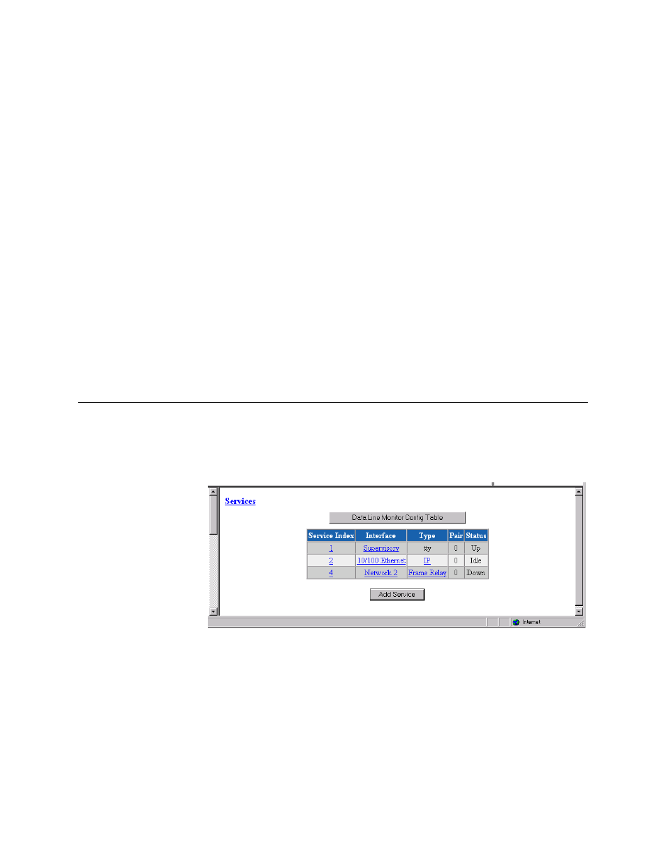
The Services screen (Figure 3.18) provides a view of the unit’s defined
services and displays the Interface, Type, and Pair parameters for each
service.
Figure 3.18
Services Screen
The Status for a particular service will display as one of the following:
•
Dead
−
The service is not functional because required resources are not
available.
•
Changed
−
The service parameter was changed and a Save and Restart is
required for the service to function.
•
Down
−
The service is not able to pass data because the physical layer is
down.