Serial screens, Serial screens -15 – Verilink WANsuite 7105 (34-00316.C) Product Manual User Manual
Page 149

V T 1 0 0 I n t e r f a c e
4-15
Serial Screens
NOTICE:
All references in this manual to the Serial 1 and Serial 2 interfaces
correspond directly to the WANsuite 7105’s Data 1 and Data 2 ports,
respectively.
The Serial screens let you view and make changes to the unit’s Serial
interface configuration as described in the paragraphs below. The parameters
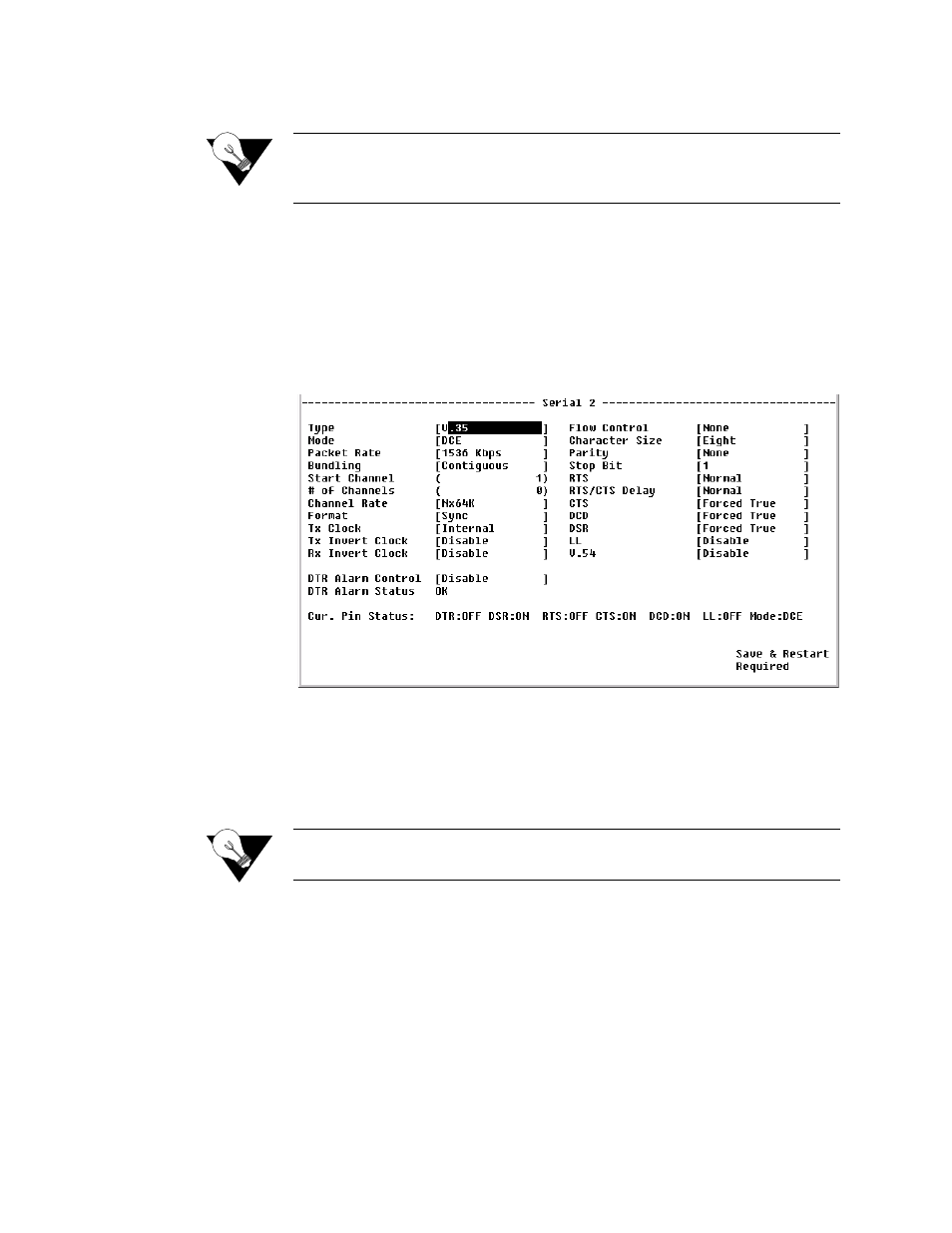
on the Serial 1 and Serial 2 screens are the same, except for the “Rx Invert
Clock” parameter, which is shown only on the Serial 2 screen (Figure 4.11).
To make changes to any Serial parameter, simply set the parameter to the
desired selection and press the “Esc” key.
Figure 4.11
Serial 2 Screen
Type
This parameter selects the type of interface (based on its electrical signal
characteristics) used by the equipment connected to the Serial port.
Values: V.35, RS-232, EIA-530, EIA-530A
Default: V.35
NOTICE:
V.35 requires the use of an optional cable. Refer to Optional Equipment
on page A-7 for ordering information.
Mode
By default, the Serial port serves as a DCE port. However, the Serial port can
serve as a DTE port when the unit is in Packet Mode.
If the Serial port connects to a DTE device (such as a FRAD or a router), the
“Mode” parameter must be set to “DCE.” If this port connects to a DCE
device (such as a DSU/CSU), this parameter must be set to “DTE” (valid only
for Packet Mode, not TDM).
Values: DCE, DTE
Default: DCE
