External antenna, Figure 58: radio modem installed in sf-3040 – NavCom SF-3040 Rev.F User Manual
Page 131
SF-3040 Product User Guide
– Rev. F
7-129
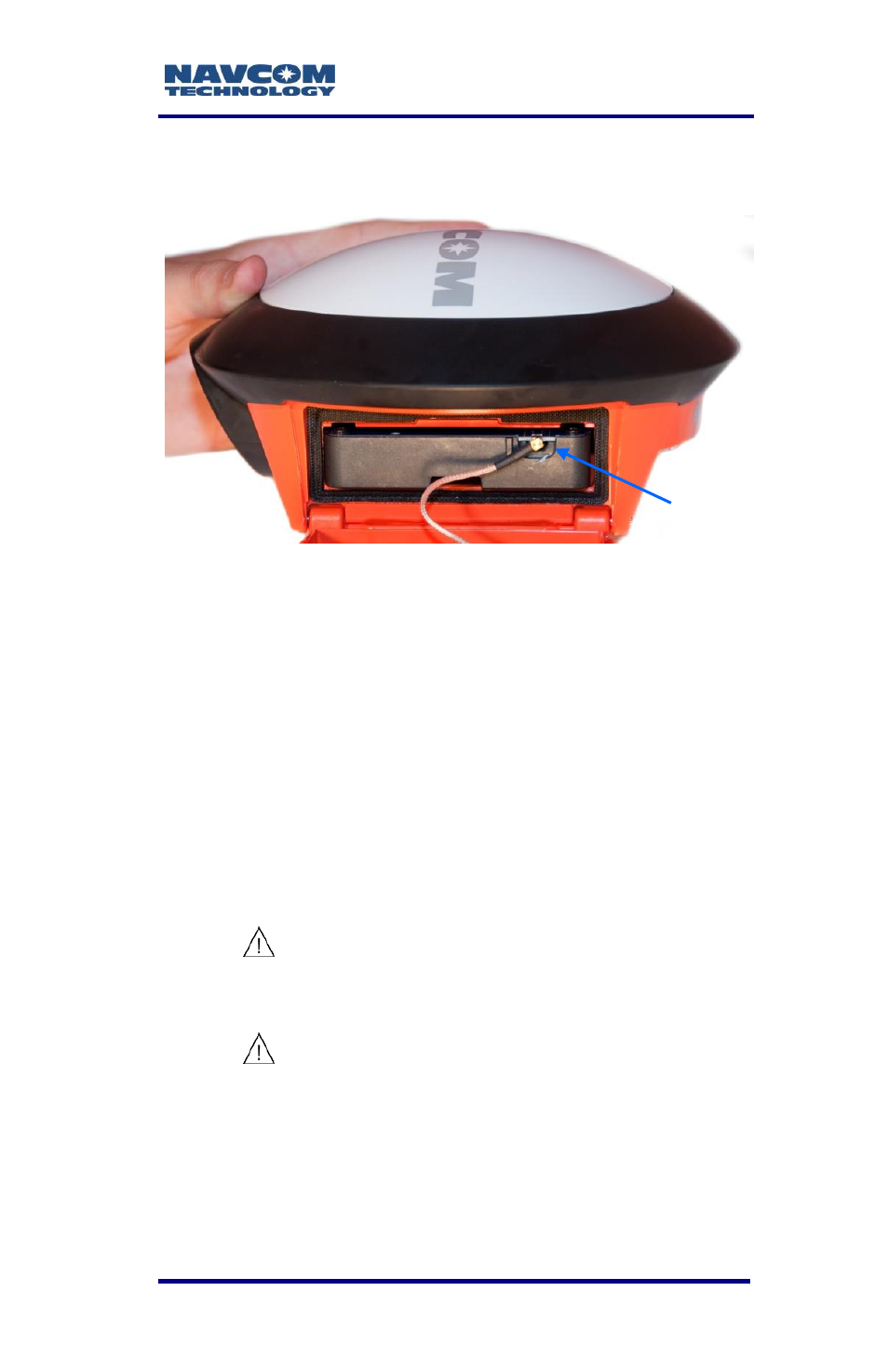
center pin and the connector will need to be
replaced.
Figure 58: Radio Modem Installed in SF-3040
7. Align the antenna cable so that it is out of the way
of the closed door.
8. Ensure that the door is in the locked position.
9. Connect the radio antenna.
External Antenna
The radio modem requires an external antenna,
which is included in the radio modem kit.
To prevent damage, the radio modem
should be switched OFF prior to
connecting or disconnecting the antenna.
Do not expose the radio modem to water
or direct sunlight.
Radio performance is contingent upon
the proper antenna selection for the
band of operation (refer to Table 21).
Cable with
MCX
connector
This manual is related to the following products: