Figure 56: radio modem chamber release button, Figure 57: radio modem installation – NavCom SF-3040 Rev.F User Manual
Page 130
SF-3040 Product User Guide
– Rev. F
7-128
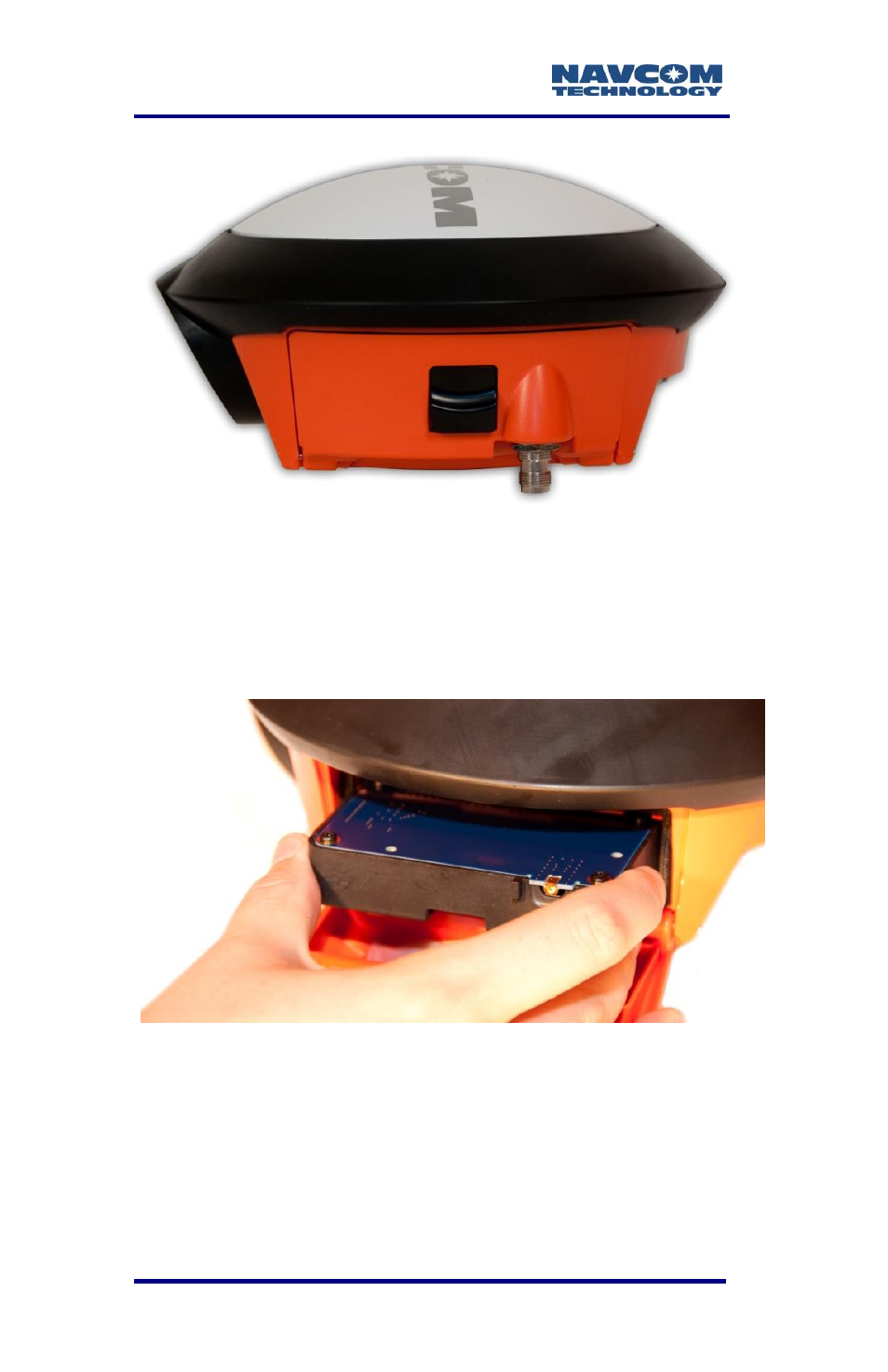
Figure 56: Radio Modem Chamber Release Button
5. With the multi-pin connector on top, fully insert the
radio modem into the module opening on the side
of the SF-3040 until you hear the radio click into
place (refer to Figure 57).
Figure 57: Radio Modem Installation
6. Carefully plug the antenna plug into the MCX
connector on the module. Be sure to align the
center pin and press the connector on straight. A
bent connector probably indicates a damaged
This manual is related to the following products: