Internal clock method – Measurement Computing Data Acquisition Systems rev.10.4 User Manual
Page 40
4 Due to processing latencies, no software trigger sources should be used when attempting to do synchronous
device acquisitions. When doing synchronous acquisitions the valid trigger modes are limited to External TLL,
Analog Hardware, and Immediate trigger sources.
Internal Clock Method
This method synchronizes the devices by sharing the same external trigger event. The external trigger
event can be either External TTL or Analog Hardware. In this method, each device still runs
independently on its own internal acquisition pacer clock but the acquisition on each device is initiated
through the same external trigger event. Using this method it is important that all the devices internal pacer
clocks are to the same rate (or at least evenly divisible by the highest rate) in order to ensure that the input
data can be temporally correlated.
As mentioned above, the DaqX API is a handle-based API. A handle-based API is an API which assigns a
unique handle to each device in use. As in the single device scenario, each device needs to be opened
using the daqOpen function. Each device should be opened using the alias name given to the device in
the Daq Configuration Utility located in the Control Panel of WindowsNT/2000/XP operating system. As
each device is opened a new, unique handle for each device is generated and returned by the daqOpen
function. The handle is a unique identifier for each device and should be used when referencing DaqX
functions for the device.
Using this model, each device needs to be configured using the appropriate handle for the device. Some
configuration parameters may differ but some parameters need to be configured specifically for this
method. Using this model, each device needs to be uniquely configured using the appropriate handle for
the device. The acquisition of the data for each device also is managed independently for each device.
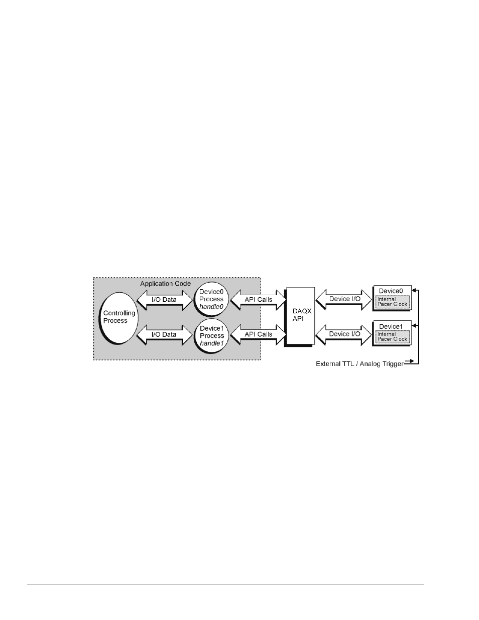
The diagram below shows how the application should operate with two devices.
Using this model, each device needs to be opened and a device handle assigned. Here the Controlling
Process would open each device session according to the device inventory list (this can be interrogated by
inspecting the device inventory in the Daq Configuration utility located in the Control Panel of the
operating system). The Control Process would then pass each device handle to the appropriate Device
Process.
Note: While the above diagram does indicate the division of responsibilities within the application, the
application may be organized in any fashion desirable. The individual processes need not be
separate tasks or threads in order for the multi-device model to work well.
For discussion purposes, the responsibilities of the Controlling Process are as follows:
1. For each device, open the device session and retrieve the device handle (see daqOpen).
2. Pass each device handle to the appropriate Device Process so that the Device Process can configure
the acquisition for its device.
3. Interleave the data from each Device Process and update any outputs as required.
4. Optionally, write the input data from the devices and write the input data for each device to disk.
3-4 Using Multiple Devices
908494
Programmer’s
Manual