Counter mode operating summary – Measurement Computing Data Acquisition Systems rev.10.4 User Manual
Page 350
D-10 9513 Counter-Timer
938295
Programmer’s Manual
The count type (cntType) parameter selects either binary or binary-coded decimal (BCD) counting. A
value of true for this parameter selects a BCD count, while a value of false will select a binary count.
Binary format accepts a 16-bit number ranging from 0 to 65,535. BCD format accepts four 8-bit numbers
representing 0 to 9, ranging from 0 to 9,999. In this format, each of the 8-bit numbers represents a
placeholder in a base-10 system—for instance, if the thousands bit is 2, the hundreds bit is 5, the tens bit is
7, and the ones bit is 9, then the value of the four bits together is 2,579.
The count repeat (cntRepeat) parameter causes the counter to re-arm after TC occurs if true, and does
not re-arm the counter after TC if false. Applications such as software re-triggerable 1-shots would
disable the repeat flag so the 1-shot occurs only after the counter arm command is sent. Other applications
(such as rate generators, square waves and hardware re-triggerable 1-shots) would enable the count repeat
so that the counter will run until disarmed.
The reload (reload), special gate(specGate)and gate control (gateCtrl)parameters can be used
together to configure the counter. Using these three commands, the counter can be configured in one of
four ways:
• If the reload parameter is set to false, then the counter will only use the contents of the load register for
counting.
• If the reload parameter is true and the special gate parameter is false, then the counter will alternate
between registers.
• If both the reload and the special gate parameters are true, and the gate control parameter is inactive, then
the counter will use the hold register for counting if the counter’s gate is high, or to use the load register if
the gate is low.
• If both the reload and the special gate parameters are true, and the gate control parameter is active, then
the operation is dependent on the gateCtrl parameter value.
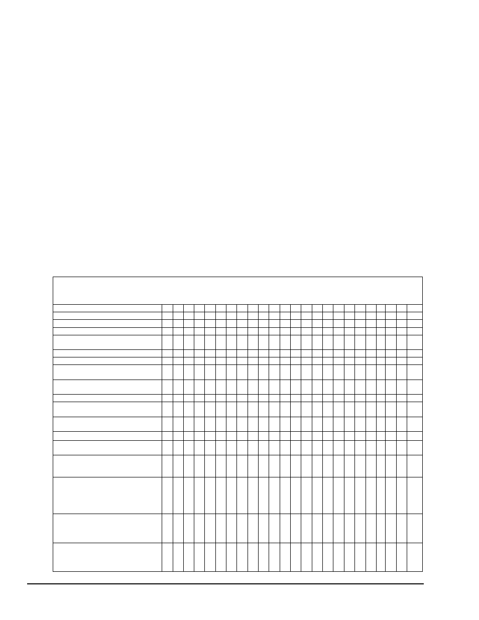
The chart below summarizes the various configurations of counter mode operation.
Counter Mode Operating Summary
Counter Mode
A B C D
E
F
G
H
I
J
K
L
M N
O
P
Q R S T U V
W X
Special Gate (CM7)
0
0
0
0
0
0
0
0
0
0
0
0
1
1
1
1
1
1
1
1
1
1
1
1
Reload Source (CM6)
0 0 0 0
0
0
1
1
1
1
1
1
0
0
0
0
0
0
1
1
1
1
1
1
Repetition
(CM5)
0 0 0 1
1
1
0
0
0
1
1
1
0
0
0
1
1
1
0
0
0
1
1
1
Gate Control (CM15-CM-13);
N=no gating; L=level; E=edge
N L E N
L
E
N
L
E
N
L
E
N
L
E
N
L E N L E N
L
E
Count
to
TC
once,
then
disarm
X
X
X
X
X
Count to TC twice, then disarm
X
X
X
X
Count to TC repeatedly without
disarming
X
X
X
X
X
X
X X
X
X
Gate input does not gate counter
input
X
X
X
X
X
X
Count
only
during
active
gate
level X
X
X
X
X
X
Start count on active gate edge and
stop count on next TC
X
X
X
X
X
Start count on active gate edge and
stop count on second TC
X
X
No
hardware
re-triggering
X X X X
X
X
X
X
X
X
X
X
X
X
X
Reload counter from Load Register
on TC
X
X
X
X
X
X
X
X
X
X
X
Reload counter on each TC,
alternating reload source between
Load and Hold Registers
X
X
X
X
X
X
Transfer Load Register into counter
on each TC that gate is LOW,
transfer Hold Register into
counter on each TC that gate is
HIGH
X
X
On active gate edge transfer
counter into Hold Register and
then reload counter from Load
Register
X
X
X X
On active gate edge transfer
counter into Hold Register, but
counting continues
X