Measurement Computing Data Acquisition Systems rev.10.4 User Manual
Page 293
Programmer’s Manual
908594
Daq API Command Reference 4.6-15
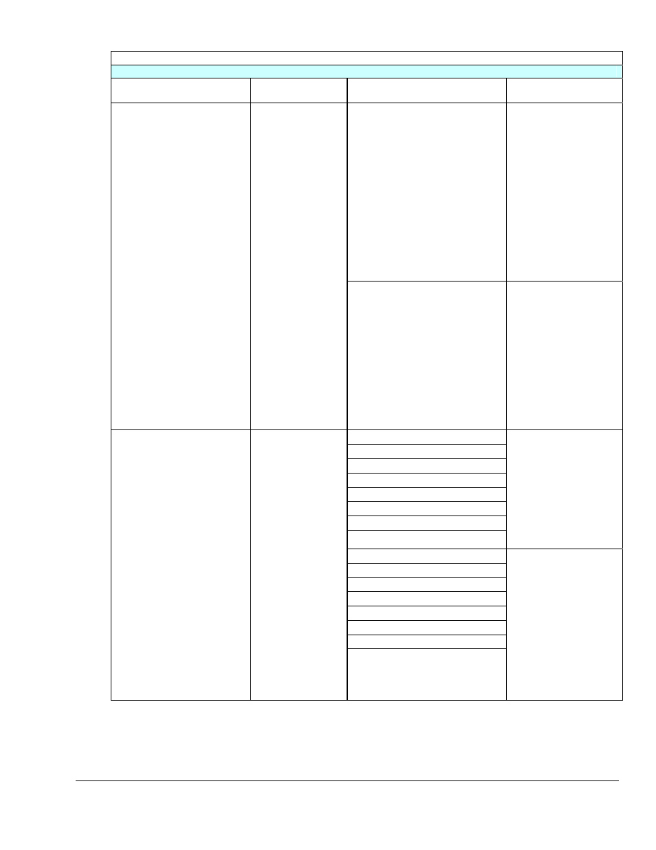
Option Type and Value Definitions Continued--DaqOptionType
WBK17 Options
(continued)
Option Type
(optionType)
Description
Option Value
(optionValue)
Description
DcovWbk17TriggerAfterStable
Selects the “Trigger After
Stable” mode. This mode
rejects glitches and only
passes state transitions after a
specified period of stability
(the debounce time). This
mode is used with electro-
mechanical devices like
encoders and mechanical
switches to reject switch
bounce and disturbances due
to a vibrating encoder that is
not otherwise moving. The
debounce time should be set
short enough to accept the
desired input pulse but longer
than the period of the
undesired disturbance.
DcotWbk17DebounceTrigger
Sets the mode of the
debounce module to
Trigger After Stable, or
to Trigger Before Stable.
DcovWbk17TriggerBeforeStable
Selects the Trigger Before
Stable mode. Use this mode
when the input signal has
groups of glitches and each
group is to be counted as one.
The trigger before stable
mode will recognize and
count the first glitch within a
group but reject the
subsequent glitches within the
group if the debounce time is
set accordingly. In this case
the debounce time should be
set to encompass one entire
group of glitches.
DcovWbk17Map_Channel_1
DcovWbk17Map_Channel_2
DcovWbk17Map_Channel_3
DcovWbk17Map_Channel_4
DcovWbk17Map_Channel_5
DcovWbk17Map_Channel_6
DcovWbk17Map_Channel_7
DcovWbk17Map_Channel_8
Selects the mapped channel to
be one of the counter input
channels.
There are 8 post-debounce
channel input signals that can
be individually selected as
mapped channels.
These are indicated as
Channel_1 for Channel 1,
Channel_2 for Channel 2, etc.
DcovWbk17Map_Detect_1
DcovWbk17Map_Detect_2
DcovWbk17Map_Detect_3
DcovWbk17Map_Detect_4
DcovWbk17Map_Detect_5
DcovWbk17Map_Detect_6
DcovWbk17Map_Detect_7
DcovWbk17Map_Detect_8
DcotWbk17MapChannel
Used to select the
mapped channel to be
either one of the counter
input channels or one of
the detection output
signals.
A mapped channel is
one of 16 signals that
can get multiplexed into
a channel’s counter
module. The mapped
channel can participate
with the channel’s input
signal by gating the
counter, clearing the
counter, etc. The 16
possible choices for the
mapped channel are the
8 input signals (post
debounce) and the 8
detection signals.
Selects the mapped channel to
be one of the detection output
signals.
Each input channel has an
associated detection signal,
e.g., Detect_1 for Channel 1.
The detection signal will go
active high when the
channel’s counter value meets
the detection module’s
setpoint criteria (programmed
into the pattern detection
module).