Measurement Computing Data Acquisition Systems rev.10.4 User Manual
Page 38
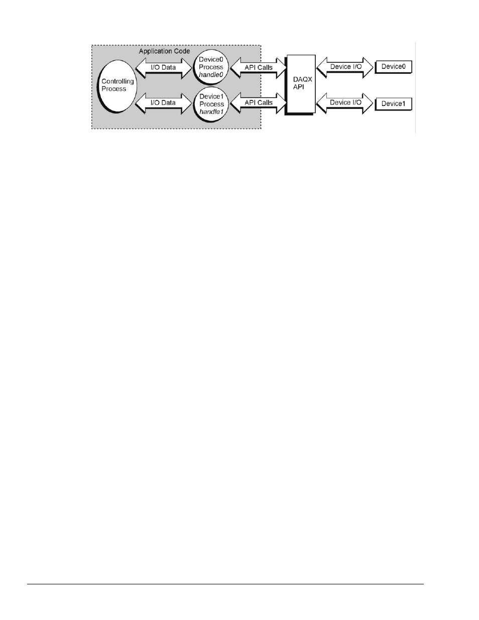
Using this model, each device needs to be opened and a device handle assigned. Here the
Controlling Process would open each device session according to the device inventory list (this
can be interrogated by inspecting the device inventory in the Daq Configuration utility located
in the Control Panel of the operating system). The Control Process would then pass each
device
handle to the appropriate Device Process so that each device process can configure
the device and acquire data from the device.
Note: While the above diagram does indicate the division of responsibilities within the
application, the application may be organized in any fashion desirable. The individual
processes need not be separate tasks or threads in order for the multi-device model to
work well.
For discussion purposes, the responsibilities of the Controlling Process are as follows:
1. For each device, open the device session and retrieve the device
handle (see daqOpen).
2. Pass each device
handle to the appropriate Device Process so that the Device Process can
configure the acquisition for its device.
3. Process any data returned from each Device Process and update any outputs required.
4. Optionally, write the input data for each device to disk.
Each device process is responsible for performing the following steps in order:
1. Configure the channel scan group for the device including expansion channels (see
daqAdcSetScan for channel scan group configuration details).
2. Configure the acquisition clocking or rate to be used (see
daqAdcSetRate and
daqAdcSetClockSource for details on scan rate clocking configurations).
3. Configure the acquisition mode to set pre-trigger, post-trigger and update mode ( see
daqAdcSetAcq for details on configuring acquisition mode parameters).
4. Configure the means by which the acquisition should start and terminate by configuring
the Trigger and Stop Events. (see
daqSetTriggerEvent for more details on configuring
the Trigger and Stop Events).
5. Configure the buffer model to be used for the device. (see
daqAdcTransferSetBuffer for
more details on configuration of the buffer model.
6. Initiate a transfer from the device (see
daqAdcTransferStart) and arm the device to
detect the trigger event (see
daqAdcArm ).
7.
Monitor the status of the input data transfer and the acquisition (see
daqAdcTransferGetStat) and optionally pass data back to the Controlling Process.
Since this section deals with asynchronous operation, each device may be independently
programmed with respect to steps 1-7. When the devices are independently programmed
each device may take on separate acquisition settings such as Trigger/Stop Events, Pre/Post-
Trigger modes and buffer model settings. Independent device operation also implies that the
data acquired from the different devices cannot be temporally correlated. As such, data from
each device should be handled separately in either separate data buffers in memory or
separate disk files. Sections to follow illustrate using multiple devices in a synchronized
manner.
3-2 Using Multiple Devices
908494
Programmer’s
Manual