Devicetype–(daqdacdevicetype), Prototypes, Program references – Measurement Computing Data Acquisition Systems rev.10.4 User Manual
Page 228: Selecting the output channel, Visual basic
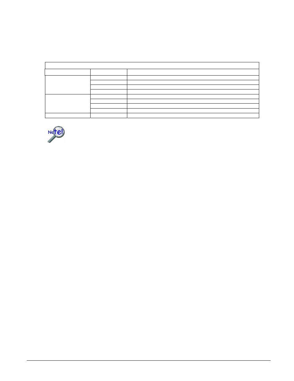
Selecting the Output Channel
The chan and the deviceType parameters determine which output channel’s voltage will be set. The
device type is represented by predefined settings described below. The channel is simply an integer (starting at
0) which represents the channel location relative to the first channel of the same type. The table below
describes this relationship:
deviceType–(DaqDacDeviceType)
Device Type
chan
Value
Description
0
Output data value to DAC0
1
Output data value to DAC1
2
Output data value to DAC2
DddtLocal
3
Output data value to DAC3
N*4 + 0
Set output for channel0 on a DBK2 or DBK5 on bank N
N*4 + 0
Set output for channel1 on a DBK2 or DBK5 on bank N
N*4 + 0
Set output for channel2 on a DBK2 or DBK5 on bank N
DddtDbk
N*4 + 0
Set output for channel3 on a DBK2 or DBK5 on bank N
DddtLocalDigital
N/A
The 16-bit P3 Digital port is not applicable for analog output operations
If using an analog hardware trigger with DaqBook, TempBook or DaqBoard(ISA)
products, the DAC channel 1 (deviceType = DddtLocal and chan = 1) is not available to be
programmed. The reason for this is that the DAC channel 1 is used to configure the trigger
level for the acquisition.
Prototypes
C/C++
daqDacWt(DaqHandleT handle, DaqDacDeviceType deviceType, DWORD chan, WORD
dataVal);
Visual BASIC
VBdaqDacWt&(ByVal handle&, ByVal deviceType&, ByVal chan&, ByVal dataVal%)
Program References
DAQEX.FRM (VB)
4.4-46 Daq API Command Reference
908494
Programmer’s
Manual