Parameter type definitions, Returns, Function usage – Measurement Computing Data Acquisition Systems rev.10.4 User Manual
Page 355: Tod-(daq9513timeofday)
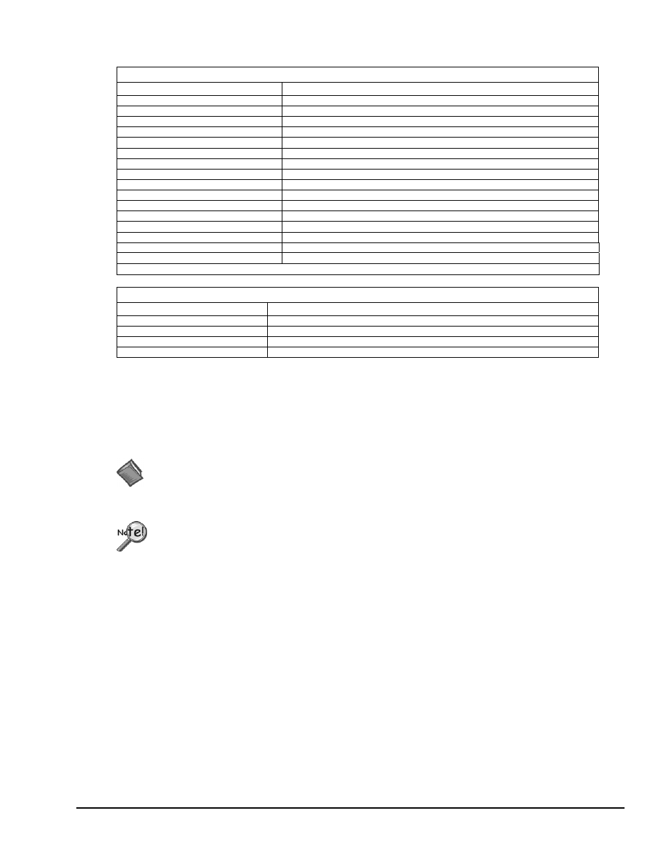
Parameter Type Definitions
cntSource-(Daq9513CountSource)
Definition Description
DcsTcnM1*
TC toggled output of previous (N-1) counter
DcsSrc1
Counter 1 input (pin36 of P3)
DcsSrc2
Counter 2 input (pin19 of P3)
DcsSrc3
Counter 3 input (pin17 of P3)
DcsSrc4
Counter 4 input (pin15 of P3)
DcsSrc5
Counter 5 input (pin13 of P3)
DcsGate1
Counter 1 gate (pin37 of P3)
DcsGate2
Counter 2 gate (pin18 of P3)
DcsGate3
Counter 3 gate (pin16 of P3)
DcsGate4
Counter 4 gate (pin14 of P3)
DcsGate5
Counter 5 gate (pin12 of P3)
DcsF1
Onboard 1 MHz Clock
DcsF2
Onboard 100 kHz Clock
DcsF3
Onboard 10 kHz Clock
DcsF4
Onboard 1 kHz Clock
DcsF5
Onboard 100 Hz Clock
*invalid with daq9513SetMasterMode
tod-(Daq9513TimeOfDay)
Definition Description
DtodDisabled
Time of day function is not used
DtodDivideBy5
A 50Hz signal is being applied to pin 36 of P3 to generate time of day input
DtodDivideBy6
A 60Hz signal is being applied to pin 36 of P3 to generate time of day input
DtodDivideBy10
A 100Hz signal is being applied to pin 36 of P3 to generate time of day input
Returns
DerrInvCntSource
Invalid
source
DerrInvTod
Invalid time of day mode
DerrInvDiv
Invalid
divisor
DerrNotCapable
No 9513 available
DerrNoError
No error
For more details on error messages refer to the Daq Error Table. The table precedes Appendix A.
Function Usage
All daq9513SetMasterMode parameters default to zero after daqOpen.
Configuring the Frequency Output Pin and Comparators
The frequency output source (cntSource) parameter selects what signal will be output on the frequency output
(fout) pin. The fout source can be any one of the following:
• the counter inputs--Src1 to Src5 (P3 pins 36, 19, 17, 15 or 13)
• the counter gates--Gate1 to Gate5 (P3 pins 37, 18, 17, 16 or 14)
• an internal frequency--F1 to F5
The sources F1 through F5 correspond to the frequencies 1 MHz, 100 kHz, 10 kHz, 1 kHz and 100 Hz.
The fout divider will divide the selected source by 1 to 16 before outputting the signal on the fout pin.
The 2 comparator flags (comp1 and comp2) control the comparators associated with counters 1 and 2. If
a comparator is set to true, the value in the corresponding alarm register (set with the
daq9513SetAlarm
function) will be compared with the value in the counter. The output of the
corresponding counter will become true when the value in the counter reaches the value in the alarm
register; the output remains true until the counter value changes. The polarity of the output depends on
the output control (set with the
Programmer’s Manual
938295
9513 Counter-Timer Commands D-15