Prototypes, Program references, Correcting data – Measurement Computing Data Acquisition Systems rev.10.4 User Manual
Page 175: Visual basic
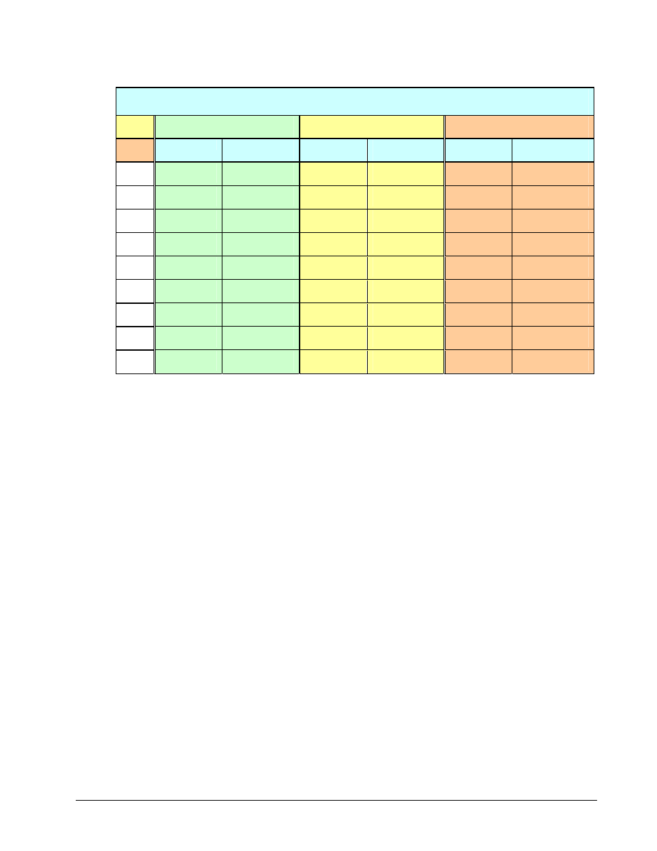
When using gain values from the preceding tables to measure TCs, the following temperature ranges apply:
Thermocouple mV Outputs For Temperature Ranges
Depending on Ambient Temperature
T/C
Type
Measured Temperature Range
@ 0°C ambient
Measured Temperature Range
@ 25°C ambient
Measured Temperature Range
@ 50°C ambient
Temp (°C)
0°C Output
(mV)
Temp (°C)
25°C Output
(mV)
Temp (°C)
50°C Output
(mV)
J
-200 to 760
-7.9 to 42.9
-200 to 760
-9.2 to 41.6
-200 to 760
-11.8 to 39.0
K
-200 to 1372
-5.9 to 54.9
-200 to 1372
-6.9 to 53.9
-200 to 1372
-8.9 to 52.9 (50.0)
T
-200 to 400
-5.6 to 20.9
-200 to 400
-6.6 to 19.9
-200 to 400
-8.7 to 17.7
E
-270 to 1000
-9.8 to 76.4
-270 to 1000
-11.3 to 74.9
-270 to 1000
-14.5 to 71.7
N28
-270 to 400
-4.3 to 13.0
-270 to 400
-5.0 to 12.3
-270 to 400
-6.4 to 10.9
N14
0 to 1300
0.0 to 47.5
0 to 1300
-0.7 to 46.8
0 to 1300
-2.0 to 45.5
S
-50 to 1780
-0.2 to 18.8
-50 to 1780
-0.4 to 18.7
-50 to 1780
-0.7 to 18.4
R
-50 to 1780
-0.2 to 21.3
-50 to 1780
-0.4 to 21.1
-50 to 1780
-0.7 to 20.8
B
50 to 1780
0.0 to 13.4
50 to 1780
0.0 to 13.4
50 to 1780
0.0 to 13.4
Correcting Data
Two software techniques (software calibration and zero compensation) can be used to increase the accuracy of
a temperature module or card.
• Software calibration uses gain and offset calibration constants, unique to each card, to compensate for
inherent errors on the card.
• Zero compensation is a method by which any offset voltage on the card can be removed at run-time. This
is done by measuring a shorted channel at the same gain on the actual input to find the offset, and
subtracting this value from the actual reading.
The thermocouple linearization function has a special auto-zero compensation feature that will perform zero
compensation on the raw thermocouple data before linearizing when using a temperature module or card. The
auto-zero feature is enabled by default, but can be disabled using the daqAutoZeroCompensate function.
It is not available when using unipolar mode.
If a temperature module or card is used with auto-zeroing enabled, the CJC channel reading described above
must be preceded by 2 readings from the shorted channel (channel 1). The first shorted reading must be at the
same gain setting as the CJC reading. The other shorted reading must be at the gain of the T/C to be converted.
If, instead, software calibration is used with the temperature module or card, the calibration constants for the
card to be used should be entered into the calibration file.
Prototypes
C/C++
daqCvtTCConvert(PWORD counts, DWORD scans, PSHORT temp, DWORD ntemp);
Visual BASIC
VBdaqCvtTCConvert&(counts%, ByVal scans&, temp%, ByVal ntemp&)
Program References
DBK19EX.CPP,DBK81EX.CPP, DBK82_83EX.CPP, DBK90EX.CPP
Programmer’s Manual
908494
Daq API Command Reference 4.3-49