Daq9513setmastermode, Format, Purpose – Measurement Computing Data Acquisition Systems rev.10.4 User Manual
Page 354: Parameter summary, Parameter values
D-14 9513 Counter-Timer
938295
Programmer’s Manual
daq9513SetMasterMode
Also See: daq9513SetLoad, daq9513MultCtrl, daq9513GetHold, daq9513SetCtrMode
Format
daq9513SetMasterMode (handle, deviceType, whichDevice, foutDiv,
cntSource, comp1, comp2, tod)
Purpose
daq9513SetMasterMode
is used to set the counter’s master mode register, which is used to configure
the frequency output pin (P3 pin 30), the comparators of counter 1 and 2, and the time-of-day operation of
the 9513 chip.
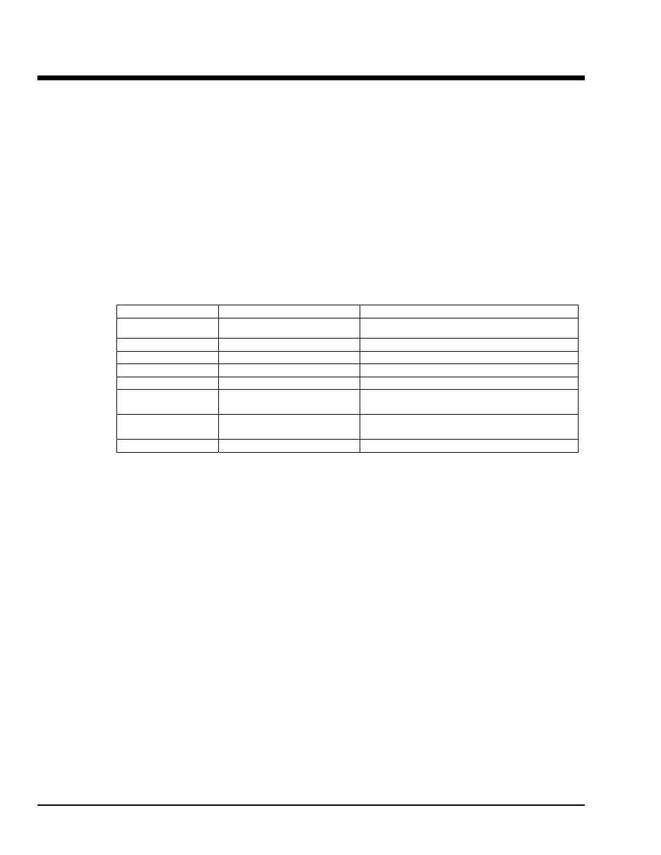
Parameter Summary
Parameter Type
Description
handle DaqHandleT
Handle to the device in which to set the 9513 master
mode
deviceType DaqIODeviceType
Specifies the 9513 device type
whichDevice DWORD
Specifies which 9513
foutDiv DWORD
The frequency output (fout) divider
cntSource Daq9513CountSource
The frequency output (fout) source
comp1 BOOL
A flag that, if
true
, will enable the compare 1
operation; if
false
, it will be disabled
comp2 BOOL
A flag that, if
true
, will enable the compare 2
operation; if
false
, it will be disabled
tod Daq9513TimeOfDay
The time-of-day mode
Parameter Values
handle:
obtained from the daqOpen function
deviceType:
must be set to value DiodtLocal9513
whichDevice:
valid value for all devices is 0
foutDiv:
valid values range from 1 to 16; 0 selects divider of 16
cntSource:
see table below
comp1:
valid values are either true (
≠ 0) and false ( = 0)
comp2:
valid values are either true (
≠ 0) and false ( = 0)
tod:
see table below