Selecting the output channel, Setting the output mode – Measurement Computing Data Acquisition Systems rev.10.4 User Manual
Page 184
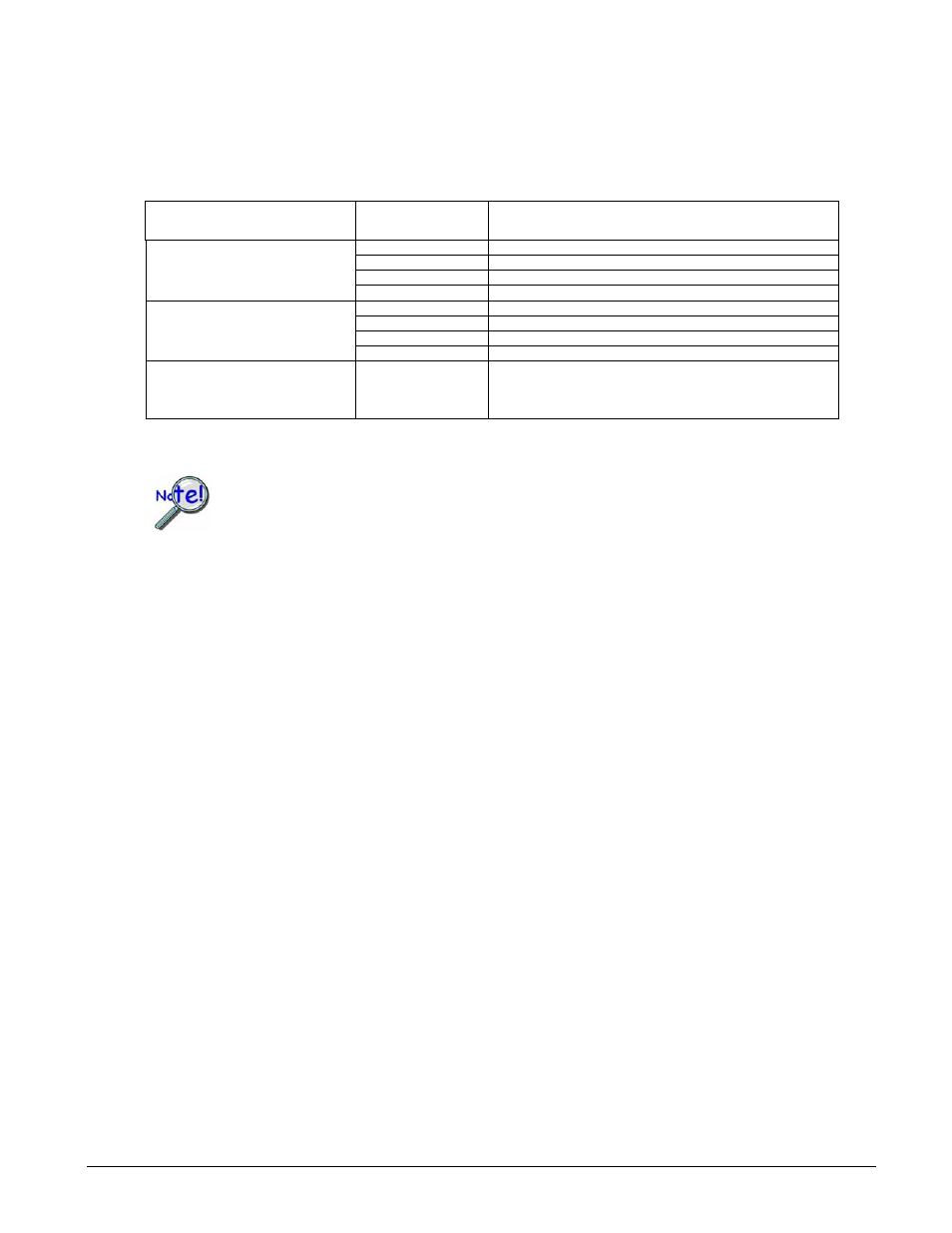
Selecting the Output Channel
The output channel for which to set the mode is determined by the chan and the deviceType parameters.
The device type is represented by predefined settings described below. The channel is simply an integer
(starting at 0) which represents the channel location relative to the first channel of the same type. The table
below describes this relationship:
Device Type
(deviceType
)
Channel
(chan)
Description
0
Set output mode for DAC0 on the main unit device
1
Set output mode for DAC1 on the main unit device
2
Set output mode for DAC2 on the main unit device
DddtLocal
3
Set output mode for DAC3 on the main unit device
N*4 + 0
Set output mode for channel0 on a DBK2 or DBK5 on bank N
N*4 + 1
Set output mode for channel1 on a DBK2 or DBK5 on bank N
N*4 + 2
Set output mode for channel2 on a DBK2 or DBK5 on bank N
DddtDbk
N*4 + 3
Set output mode for channel3 on a DBK2 or DBK5 on bank N
DddtLocalDigital
0
Set Output Mode for the local P3 16-bit DIO channel on the main
unit. This setting only applies when using the local P3 16-bit DIO
channel for streamed output.
Setting the Output Mode
The term waveform/pattern output is used extensively throughout the entries for the
functions of the form daqDac…. This refers to an analog waveform output modes and/or
digital pattern output modes. These terms describe output to digital-to-analog converter
(DAC) channels and/or digital input/output (DIO) channels that are synchronously
updated by a clock source defined by the application.
The outputMode parameter indicates the type of output update to be performed on the specified
DAC/Digital output channel. Generally, the output mode is either direct, asynchronous update or a
waveform/pattern output.
There are two basic types of waveform/pattern output. One is a static mode that allows downloading the entire
waveform/pattern output buffer to the internal FIFO on the device for unattended output. The other is a
dynamic mode that allows continuous update of the output by the application. The settings for all of the
possible modes are as follows:
DdomVoltage–
Specifies a single, DC voltage or current output mode. This mode defines the output of the
specified DAC channel to be updated only when written to explicitly. The valid range over which actual
voltage and current values can be written to the port depends upon the specified range of the local DAC device
or the DBK2 or DBK5 (see output range specifications for your device). When this mode is set with the
daqDacSetOutputMode
function, no change to the current output state of the channel will be performed.
See daqDacWt and daqDacWtMany for the actual writing of the DAC channel values. No waveform/pattern
outputs can be generated for the specified channel while the channel is in the DdomVoltage mode. This
setting represents the default setting for all channels.
4.4-2 Daq API Command Reference
908494
Programmer’s
Manual