Measurement Computing Data Acquisition Systems rev.10.4 User Manual
Page 14
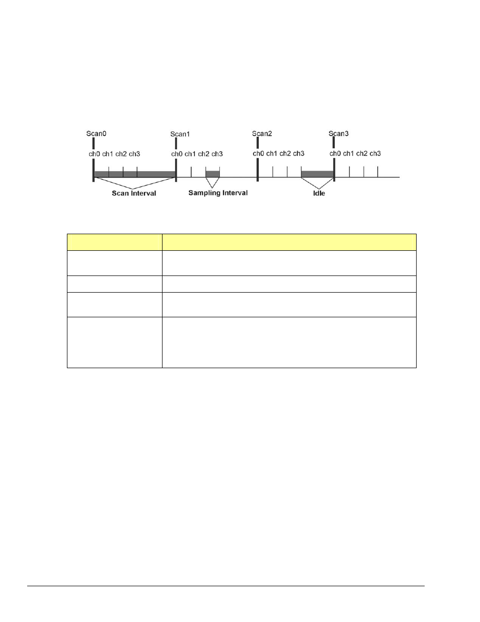
3. Set the Acquisition Rate – How Fast Should Channels be Scanned?
In this section we describe how to configure the rate at which data is acquired for your
acquisition. Here the acquisition rate refers to the rate at which channel scans are acquired.
Depending upon which API is used the acquisition scan rate can be selected by either
frequency or period/interval. Note that the rate being programmed is the rate at which the
entire channel
scan is paced. For all Daq devices the scan pacing can be derived from either
an internal clock or an external clock driven by an input controlled by an external source. The
between-channel sampling interval is normally a fixed interval depending upon the type of
device used. Daq devices are normally fixed at 10us sampling interval. The between-channel
sampling interval for /2000 Series devices is software selectable for either 5us or 10us.
err = daqAdcSetFreq(handle, 1000.0);
Related API’s*
Description
daqAdcSetFreq
Sets the acquisition rate for both pre-trigger and post-trigger
acquisitions in Hz based off of the internal pacer clock of the device
daqAdcGetFreq
Returns the current acquisition rate setting.
DaqAdcSetClockSource
Sets the acquisition base clock source to either the internal pacer or
to an external clock source.
daqAdcSetRate
Allows setting pre and post-trigger scan rates in either period or
frequency format (pre-trigger rate cannot be set for most Daq
device products, for Daq device products pre-trigger rate will follow
post-trigger rate). This command may also be used to return
current pre-trigger and post-trigger rate settings.
*See the
API Command Reference chapter for detailed information.
4. Setting up the Data Buffer Model – How Should the Data be Stored?
In this section we describe how to configure the buffer model to be used for the acquisition.
There are two basic buffer models from which to choose; the User Buffer Model and the Driver
Buffer Model.
The User Buffer Model allows the user or application to allocate a buffer and pass the
information describing the location and disposition of the buffer down to the driver so that the
driver can place collected data into the buffer. However, the User Buffer Model requires that
the maintenance of the buffer and buffer pointers be performed by the user or application.
When using the User Buffer Model the application can query the driver as to the total amount
of data that has been transferred into the buffer but the user/application is responsible for
maintaining and updating the current read and write pointers into the buffer. The User Buffer
Model can employ either linear or circular buffers depending on the needs of the application.
The Driver Buffer Model the user/application to hand off responsibility of buffer management
to the driver.
WORD buffer[SCANS * CHANCOUNT];
err = daqAdcTransferSetBuffer(handle, buffer,SCANS, DatmDriverBuffer);
2-4 API Programming, General Models
988594
Programmer’s
Manual