Measurement Computing Data Acquisition Systems rev.10.4 User Manual
Page 119
Function Usage
Transfer Buffer Location
The buf parameter is the address of the acquisition transfer buffer allocated by the application. If the
application is supplying the buffer then this value must be an address to an adequately allocated buffer.
Transfer Buffer Length
The scanCount parameter is the total length of the transfer buffer in scans. The size of a scan is determined
by the total number of channels in the scan group configuration (see daqAdcSetScan and daqAdcSetMux
for further information on scan group configuration). Therefore, the buffer size to be allocated (in bytes):
scanCount
* scan size (number of channels) * sample size (normally 2 bytes)
If using packed mode with a WaveBook/512, the above calculation should be multiplied by
¾ to determine actual buffer allocation size required.
Transfer Buffer Settings
The character of the transfer buffer can be configured via the transferMask parameter. This parameter is a
bit mask parameter--it can take on a number of settings, each dependant on how the values are joined logically
with either OR or AND (see the “Mask and Flag Definitions” section). Among other things, the
transferMask
parameter specifies the update, layout/usage, and allocation modes of the buffer. The
parameter’s possible values are defined as follows:
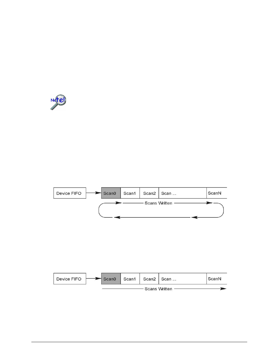
DatmCycleOn
– This parameter value defines the buffer as a circular buffer in buffer-cycle mode. This
allows the transfer to continue when the end of the transfer buffer is reached by wrapping the transfer of
acquisition data back to the beginning of the buffer, as shown in the diagram below.
In the circular buffer mode, the acquisition transfer buffer will continue to be wrapped until the post-trigger
count has been reached (specified by daqAdcSetAcq) or the transfer/acquisition is halted by the application
(with the functions daqAdcTransferStop and daqAdcDisarm).
DatmCycleOff(default)
– This parameter value defines the buffer as a linear buffer. This causes the
transfer to continue to the end of the transfer buffer, at which point it will terminate.
In the linear buffer mode, no more data will be transferred once the end of the buffer has been reached,
regardless of whether an acquisition is still active. If using this mode, the application needs to ensure that
another buffer is allocated if the acquisition is going to continue beyond the end of the transfer buffer.
Programmer’s Manual
908594
Daq API Command Reference 4.2-63