Fluke Biomedical ProSim 6 User Manual
Page 51
Vital Signs Simulator
How to Simulate Cardiac Output
39
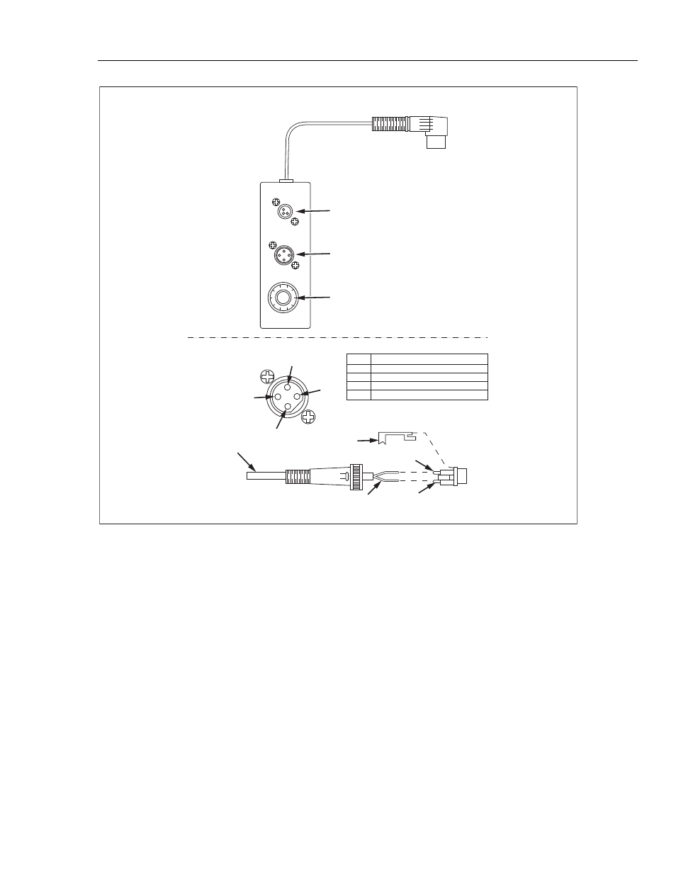
Blood temperat
u
re (BT) connector
Injectate temperat
u
re (IT) thermistor connector
Injectate temperat
u
re (IT) 10-t
u
rn potentiometer
CI-3 mod
u
le/ca
b
le
2
1
4
3
Pin1
Pin3
Crimp t
ub
e
Thermistor end of ca
b
le
ASSEMBLY of the GE
N
ERAL PURPOSE CO
NN
ECTOR
V
ie
w
ed from
the top of
the C1-3
PI
N
1
FU
N
CTIO
N
I
N
JECTATE THERMISTOR CO
NN
ECTIO
N
A
Injectate temperat
u
re (IT) thermistor connector
I
N
JECTATE THERMISTOR CO
NN
ECTIO
N
B
2
N
O CO
NN
ECTIO
N
4
N
O CO
NN
ECTIO
N
3
Solder
w
ires to pins 1 and 3
eic224.eps
Figure 28. Cardiac Output Injectate Cable Modification
Note
Fluke Biomedical offers optional adapter cables to connect the Product to
specified brands of cardiac output measurement devices.
•
To examine Hewlett Packard Merlin systems, a cardiac output adapter
and a temperature adapter are necessary.
•
A special adapter is necessary for Gould/SpectraMed Models SP1445
and SP1465 cardiac output devices.
Contact Fluke Biomedical for availability, price, and part number.
For cardiac output simulation, use the supplied CI-3 module/cable to connect the Product
to the DUT. (see Figure 29). If necessary, use the general-purpose connector.