Breaker operations counter, Breaker resistor diagnostics, Figure 4-10. output 13 logic – Basler Electric BE1-BPR User Manual
Page 86
4-34
BE1-BPR Functional Description
9272000990 Rev J
The breaker operations counter logs the number of open and close cycles of the circuit breaker. The
counter increments when the breaker closes. The number of breaker operations can be viewed or set
through the communications ports using the BKROPS command or through the HMI using Breaker Status
sub-screen 3. Breaker operations can also be viewed on the Breaker Status Menu Screen. The BKROPS
command also defines the logic for determining the breaker position (open or closed). Refer to the
Breaker Status Screen sub-section for information about using the BKROPS command.
Breaker Operations Counter
Breaker-opening resistors are used on some high voltage breakers to limit the maximum interrupting
current during fault conditions. This resistor is mechanically linked to the main breaker contact so that
when the main breaker contact opens, the opening resistor is placed in series with the phase current
approximately one-half cycle before the breaker opens. Since the breaker resistor is usually much larger
than the fault resistance, the breaker resistor will tend to limit the fault current to a value based on the
primary circuit voltage divided by the breaker resistor value ( Ires = V
LN
/ R ). This value, Ires, will be less
than the maximum short circuit rating (I
SC
) for the breaker.
Breaker Resistor Diagnostics
Typically, a breaker-opening resistor will be rated to allow a maximum number of operations (MAXOPS)
before waiting a defined reset or cooling off period. This reset period must occur before another operation
can safely be allowed. The BE1-BPR keeps track of the accumulated resistor heating by adding one
operation to the RESOPS counter for every breaker opening and subtracting one from the RESOPS
counter,
The breaker resistor counter, RESOPS, stores in volatile memory the accumulated breaker operations
that are not reset. The current status of this counter is displayed on BREAKER STATUS menu,
sub_screen 2.
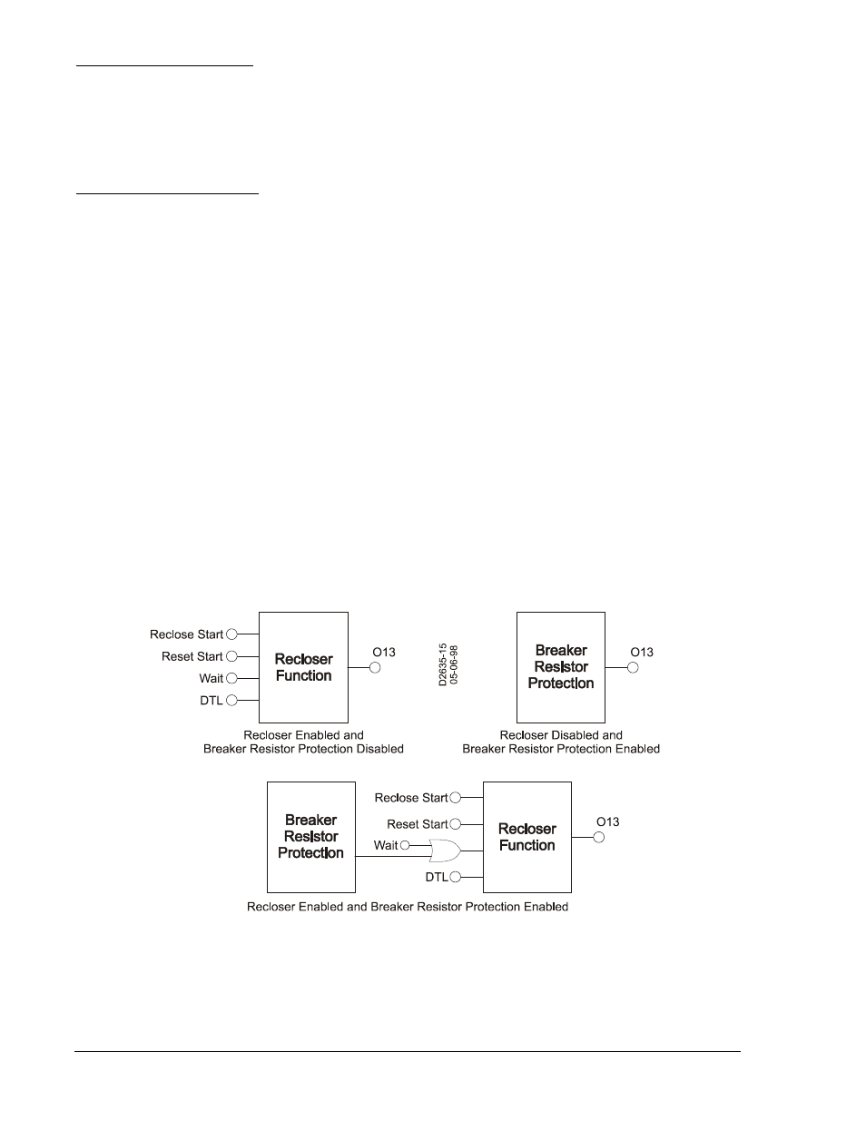
If reclosing is disabled and the accumulated operations equals MAXOPS, virtual output 13 (O13)
becomes true. This virtual output may be connected to an actual output by programming the logic. This
output contact can provide a block reclose output (BRO) to prevent another operation and overheating
the opening resistors. If the reclosing function is enabled, and the accumulated operations equals
MAXOPS, the block reclose signal is internally ORed with the defined WAIT logic input. This action delays
reclosing to protect the opening resistors from overheating. Figure 4-10 illustrates the logic that controls
virtual output 13 (O13) when breaker resistor protection and/or reclosing is enabled.
Figure 4-10. Output 13 Logic