Breaker arc detector, Breaker arc detector -9, Figure 2-11. trip circuit monitor with bfi sensing – Basler Electric BE1-BPR User Manual
Page 33
9272000990 Rev J
BE1-BPR Application
2-9
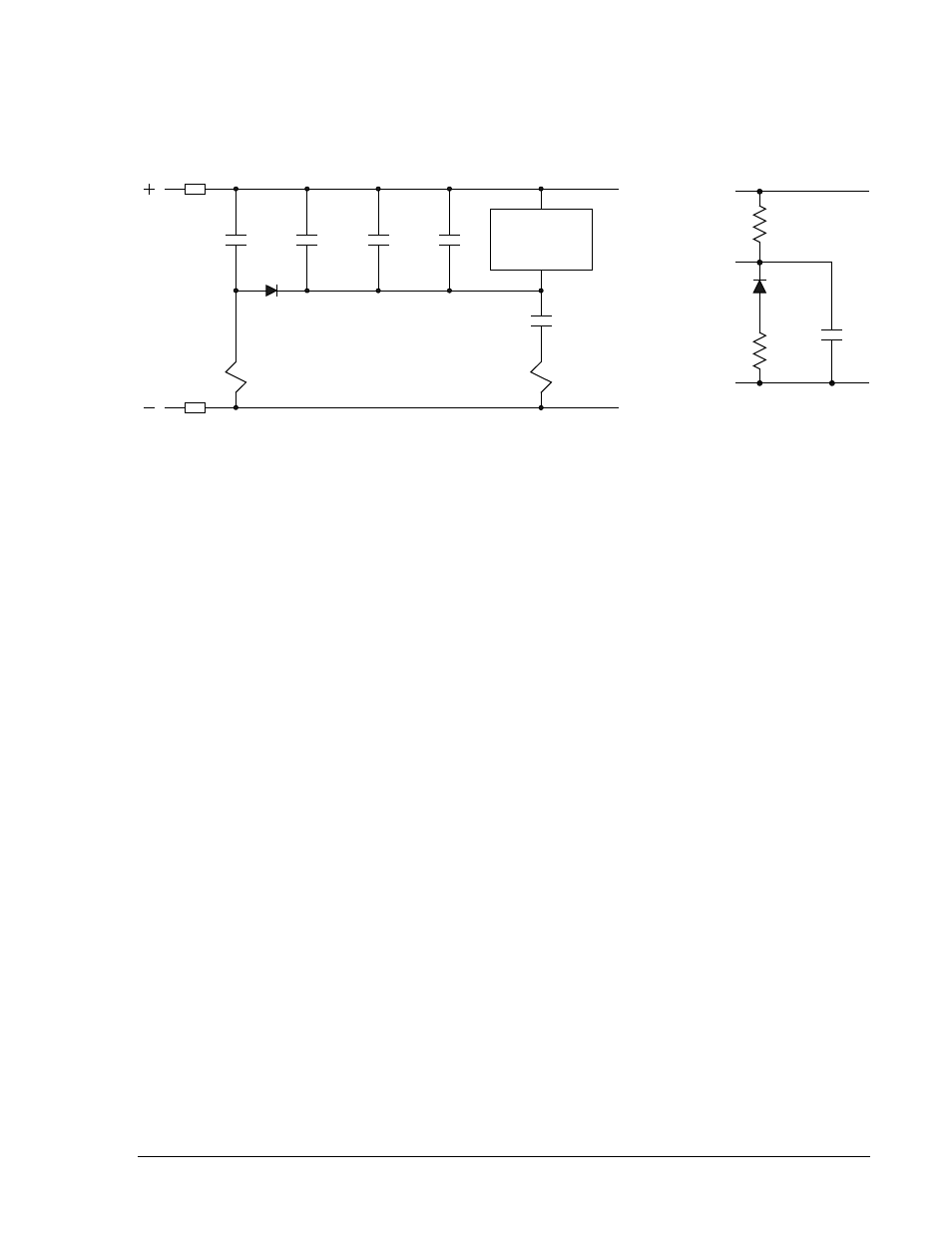
Figure 2-11 illustrates a problem that can occur when using the trip circuit monitor feature. If the breaker
failure initiate (BFI) sensing is connected directly to the breaker trip bus as shown in Figure 2-11a, the
equivalent circuit shown in Figure 2-11b occurs. If the diode of the circuit is not included, a voltage divider
circuit will be created between the BFI sensing and the TCM sensing when the 52a contact or the trip coil
is open.
Figure 2-11. Trip Circuit Monitor with BFI Sensing
In Figure 2-11a, a 62x BFI auxiliary relay is shown. In this case, the impedance of the 62x coil will be
small compared to the impedance of the TCM circuit so the TCM will always be at logic 1. This will
prevent the TCM logic from working, even if the trip coil is open. In the case that the high impedance BFI
sensing input of the BE1-BPR is connected directly to the trip bus, the TCM and the BFI impedances will
be of similar magnitude causing the voltage to be divided nearly equally. This can result in spurious BFI
signals to the breaker failure protection scheme when the breaker is open. Normally, when redundant
systems are used, each relay system will be on its own circuit and the BFI sensing for each relay system
will be isolated from the tripping circuit so this is not a problem.
Breaker Arc Detector
Once a breaker is open, an arc or flashover from a lightning strike may occur if the surge suppressors fail
or air pressure is lost in an air blast circuit breaker. If this arc is not extinguished, the breaker can be
damaged or destroyed. If the breaker was opened due to a fault on the line, then protective relays on the
line will operate. If the line is not cleared, the relay logic will trip the backup breakers to clear the line and
save the breaker.
If both ends of the line are open with no fault, then the breaker may just be carrying low level, line
charging current. This current will not operate the protective relays because it is well below the normal
loading levels. However, it is enough to destroy the breaker if not cleared. To provide protection for this
situation, a very sensitive fault detector is needed that operates at line charging current levels and is only
enabled when the breaker is open. When the fault is detected, the arc can be cleared by reclosing the
breaker or operating backup protection for breaker failures. Reclosing will not affect safety of personnel if
normal working practices are followed to disconnect any sections of the line being worked on (the line
would be energized by the arc in any case). If the breaker reclosed into a faulted line, the normal
protection devices would immediately re-open the line.
The BE1-BPR relay has a sensitive low level pickup for this application (MAF fault detector). Figure 2-12
shows the breaker arc detector circuits with the three-phase MAF fault detector (F3). It is easy to inhibit
the relay based on the breaker status by programming the relay logic. As discussed previously in the fault
detector application paragraphs, the MAF fault detector filter is slow to pickup and dropout. Therefore, the
fault detector response must be delayed to allow time for normal load or fault current to clear the filter
section. For example, if a 60 cycle MAF fault detector is used and set at 0.1 ampere (below line charging
current levels), then the MAF fault detector remains picked-up for 1 second after the breaker opens
because it takes that long for the filter buffer to clear. Therefore, the MAF fault detector output must be
delayed for a time longer than the filter length to ensure that only a sustained current signal causes an
output. This delay time could be 20 to 30 seconds longer.
52a
N
P
T
BFI
or
62X
TCM
+
V
-
+
V
-
86
Breaker
Retrip
O5
IOIT
21
IN2 (TCM)
Trip Ckt 1
Sense
P
T
52a
52TC1
N
62X
a. Schematic Diagram
b. Equivalent Voltage
Divider Circuit
D
28
22
-0
9
08
-0
7-
98