Communication connectors and settings, Front/rear rs-232 connectors, Communication connectors and settings -11 – Basler Electric BE1-BPR User Manual
Page 151: Front/rear rs-232 connectors -11, Figure 7-11. rs-232 pin-outs, Table 7-2. rs-232 pinouts (port0 and port1a)
9272000990 Rev J
BE1-BPR Installation
7-11
COMMUNICATION CONNECTORS AND SETTINGS
Front/Rear RS-232 Connectors
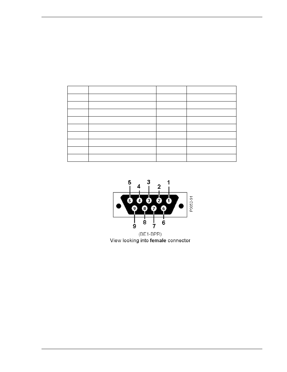
Front and rear RS-232 connectors are DB-9 female connectors. Connector pin numbers, functions,
names, and signal directions are shown in Table 7-2. RS-232 pin-outs are shown in Figure 7-11. Figures
7-12 through 7-15 provide RS-232 cable connection diagrams. Each connection diagram shows the
gender of the device or relay connector that the cable mates with. Asterisks (*) in each diagram mark
optional Clear to Send (CTS) and Request to Send (RTS) connections. These connections are required
only if hardware handshaking is enabled.
Table 7-2. RS-232 Pinouts (Port0 and Port1A)
Pin
Function
Name
Direction
1
Shield
—
N/A
2
Transmit Data
TXD
From Relay
3
Receive Data
RXD
Into Relay
4
N/C
—
N/A
5
Signal Ground
GND
N/A
6
DCE Ready
DSR
From Relay
7
Clear to Send
CTS
Into Relay
8
Request to Send
RTS
From Relay
9
N/C
—
N/A
Figure 7-11. RS-232 Pin-Outs