Breaker failure logic 1 for standard relays (bfl1), Figure 5-4. bfl1 logic diagram – Basler Electric BE1-BPR User Manual
Page 117
9272000990 Rev J
BE1-BPR BESTlogic Programmable Logic
5-11
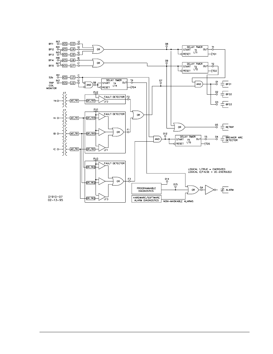
Breaker Failure Logic 1 for Standard Relays (BFL1)
Figure 5-4. BFL1 Logic Diagram
LN=BFL1
LI6=4,12
LOA=T4+O15 ∗
LO9=I6+I7
LF1=PI,1
LI7=4,12
LO1=T1O7
LO10=0
LF2=NI,1
LR=0,0,0,0,0
LO2=T2
LO11=0
LF3=PI,2
LT1=D,O8,/O8
LO3=T1O7
LO12=F3I1
LI1=4,12
LT2=D,O9,/O9
LO4=T5
LI2=4,12
LT3=0,0,0
LO5=O8+O9
LI3=4,12
LT4=D,O6,/O6
LO6=/I1/I2
LI4=4,12
LT5=D,O12,/O12
LO7=F1+F2
LI5=4,12
LT6=0,0,0
LO8=I3+I4+I5
∗
The non-maskable alarms ORed with the programmable diagnostics to provide an alarm output.
This manual is related to the following products: