General purpose timers, Delay timer, General purpose timers -5 – Basler Electric BE1-BPR User Manual
Page 29: Figure 2-5. multiple breaker arrangement, Figure 2-6. delay timer operation
9272000990 Rev J
BE1-BPR Application
2-5
Low Level Current Detector. If the breaker fails while being opened for normal load switching or due to re-
strike after the line has been isolated, the currents flowing across the failed interrupter may be too low to
reliably detect by conventional means. The Type 2 fault detector’s moving average filter allows the BE1-
BPR to discern the low level line charging current from random noise. The application of this fault detector
is described in detail in the Breaker Arc Detector sub-section. Fault detector F3 is programmed as a
phase MAF fault detector in all pre-programmed logic schemes.
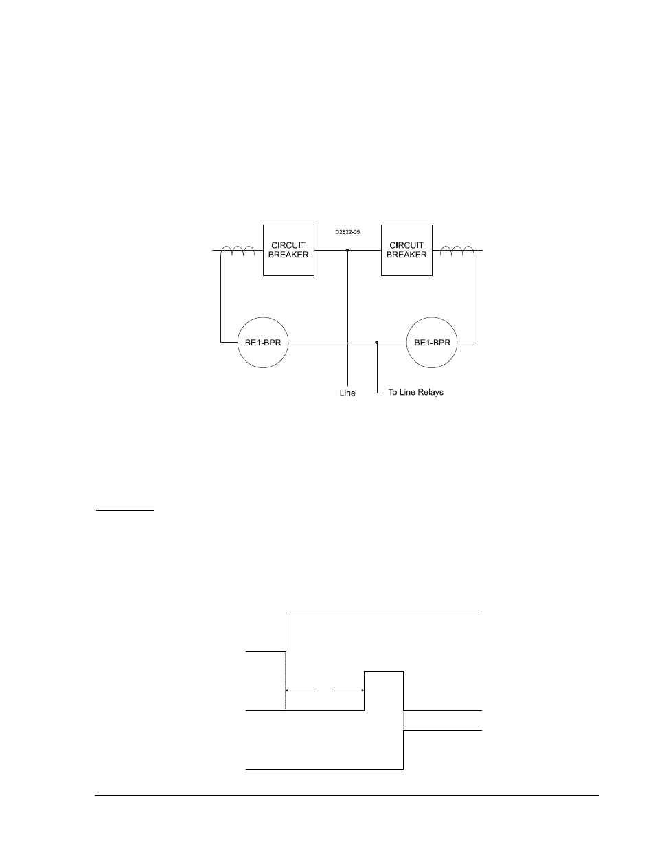
Multiple Breaker Arrangements. In ring bus and breaker and half bus applications, CTs from two breakers
are often connected in parallel. If the BE1-BPR is connected to these CTs as shown in Figure 2-5, low
fault detector pickup settings should be used with caution. In this arrangement, the CT feeding the BE1-
BPR can be energized on the secondary side from the CT on the adjacent circuit breaker. This results in
current flowing in the BE1-BPR even when the protected circuit breaker has successfully interrupted the
fault. This secondary excitation current is generally negligible except when flux remnants or high
current/burden causes the CT to saturate.
Figure 2-5. Multiple Breaker Arrangement
General Purpose Timers
Each BPR relay provides six independent timers for breaker failure timing and diagnostics. Each timer
can be programmed as a delay or a control timer and can have independent START and RESET
conditions. Each timer can also provide a diagnostic log and/or alarm. These features are explained in the
following paragraphs.
A Delay timer has two inputs START and RESET, and one output T[n]. The timer will not start until the
start condition becomes TRUE and the RESET input is FALSE. Once the timer is started, a pre-
programmed time delay, TD[n], is loaded and the timer starts timing out. Toggling of the START input has
no effect once the timer is started. The timer times out TD[n] time after the timer is started unless the
timer is RESET before the time expires. If the timer times out, then the T[n] output becomes TRUE. After
timeout, T[n] remains TRUE until the timer is RESET. Delay timer operation is illustrated in
Delay Timer
Figure 2-6. Delay Timer Operation
INITIATE
OUTPUT
RESET
TD[n]
D2635-11