Figure 7-10. contact sensing jumpers location, Table 7-1. contact sensing turn-on voltage – Basler Electric BE1-BPR User Manual
Page 150
7-10
BE1-BPR Installation
9272000990 Rev J
Each BE1-BPR is delivered with the contact sensing jumpers installed for operation in the lower end of
the control voltage range. If the contact sensing inputs are to be operated at the upper end of the control
voltage range, the jumpers must be changed or removed. Table 7-1 lists the turn-on voltage range for
each control voltage range and jumper position.
The contact sensing jumpers are used to select the lower or upper sensing range for each contact input
circuit. These jumpers ensure that the input will be off below 55 percent of nominal battery voltage and on
above 80 percent of nominal battery voltage.
Table 7-1. Contact Sensing Turn-On Voltage
Nominal Control Voltage
Turn-On Range
Pin 1 - Pin 2
Pin 2 - Pin 3
48/125 Vac/Vdc
26 to 38 V
69 to 100 V
125/250 Vac/Vdc
69 to 100 V
138 to 200 V
The following paragraphs describe how to locate and remove or change the contact sensing input
jumpers.
1. Remove the drawout assembly by rotating the two captive, front panel screws counterclockwise and
then sliding the assembly out of the case. Observe all electrostatic discharge (ESD) precautions
when handling the drawout assembly.
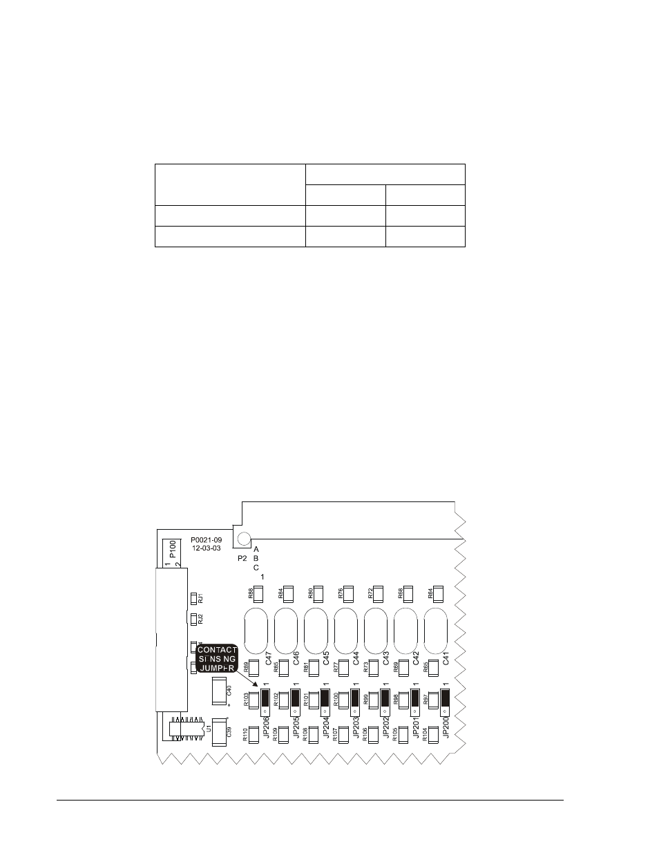
2. Locate the seven jumper terminal blocks (JP200 through JP206) that are mounted on the Logic
Circuit Board. The jumper terminal blocks are located on the component side of the circuit board near
the left hand side (right-hand side when looking at the unit from the rear). Each terminal block has
three pins and each jumper is installed at the factory on pins 1 and 2. Figure 7-10 illustrates the
location of jumpers placed for operation in the lower end of the control voltage range.
3. To select operation at 125 Vdc, remove the jumper entirely from the unit or position it on pins 2 and 3.
4. When all jumpers are positioned for operation in the desired sensing voltage range, prepare to place
the drawout assembly back into the case.
5. Align the drawout assembly with the case guides and slide the assembly into the case.
6. Rotate the two captive front-panel screws clockwise to secure the drawout assembly in the case.
Figure 7-10. Contact Sensing Jumpers Location