4 rs-485 interface, 5 programming the m131 unit (example), Rs-485 interface -4 – AMETEK M130 User Manual
Page 96: Programming the m131 unit (example) -4, 4 rs-485, M131
Operation with M131 Option
Sorensen Ethernet Option
5-4
M130/M131 Programming Manual
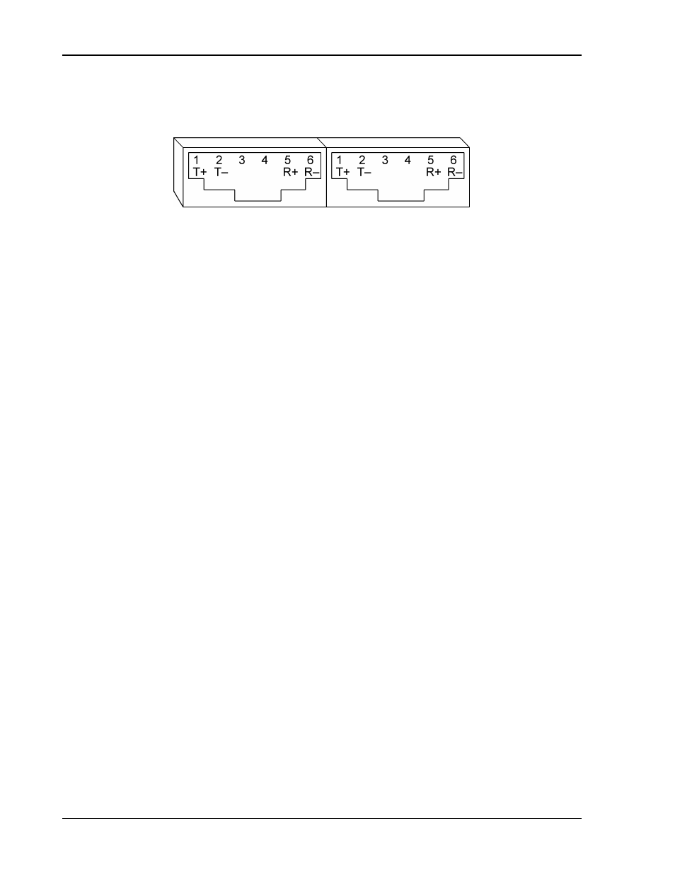
5.4 RS-485
I
NTERFACE
The RS-485 interface is accessible through the two rear-panel, 6-pin, RJ-11
connectors, J1 and J2, depicted in Figure 5-4.
Figure 5-4. M131 Rear Panel RS-485 Connectors Pinout
5.5 P
ROGRAMMING THE
M131
U
NIT
(E
XAMPLE
)
The following example programs the M131 unit to:
• Turn on
• Initialize to 2 VDC, at 1A
• Set overvoltage protection level at 3 VDC
• Verify proper power-on initialization
• Save and store changes.
// Use SYST:ERR? after each command to verify no programming errors.
// turn on the unit.
*CLS
// clear the unit to its power on default settings.
*RST
// reset the unit.
CAL[n]:INIT:CURR 1.0
// set power-on initial current to 1.0A.
CAL[n]:INIT:CURR?
// confirm power-on initial current setting.
CAL[n]:INIT:VOLT 2.0
// set power-on initial voltage to 2.0V.
CAL[n]:INIT:VOLT?
// confirm power-on initial voltage setting.
CAL[n]:INIT:VOLT:PROT 3.0
// set power-on initial overvoltage protection to 3.0V.
CAL[n]:INIT:VOLT:PROT?
// confirm power-on initial overvoltage protection setting.
CAL[n]:UNLOCK “6867”
// unlock nonvolatile memory for calibration value storage.
CAL[n]:STORE
// store the calibration values in nonvolatile memory.
CAL[n]:LOCK
// lock nonvolatile memory for calibration value protection.
// cycle power to unit.
// note voltage is initialized to 2.0 VDC via front panel.
SOUR[n]:CURR?
// confirm power-on initial current setting.
SOUR[n]:VOLT?
// confirm power-on initial voltage setting.
SOUR[n]:VOLT:PROT?
// confirm power-on initial overvoltage protection setting.