2 m131 (slave) option, M131 (slave) option -6, Figure 2-4 – AMETEK M130 User Manual
Page 24: H figure 2-4
Sorensen Ethernet Option
2-6
M130/M131 Programming Manual
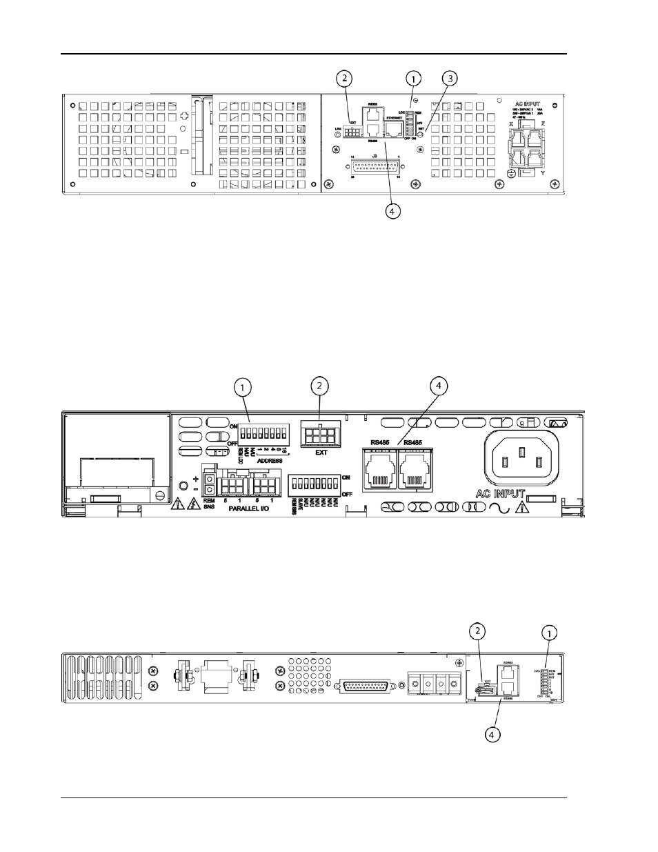
Figure 2-4. Typical Rear Panel of M130 Option for DCS3k
2.2.2
M131
(S
LAVE
)
O
PTION
Figure 2-5 through Figure 2-7 display the pertinent rear panel components of a
typical M131 Ethernet option for the DLM600 and the DCS slaves.
Figure 2-5. Typical Rear Panel of M131 Ethernet Option for DLM600
1 – Configuration Switch (for correct settings see Section 5.2)
2 – External User Control Signal Connector (see Section 2.3)
4 – Connections (RJ-11) for RS485
Figure 2-6. Typical Rear Panel of M131 Ethernet Option for DCS1k and DCS1.2k
This manual is related to the following products: