Table 5-1 definitions of s1 switch settings -2 – AMETEK M130 User Manual
Page 94
Operation with M131 Option
Sorensen Ethernet Option
5-2
M130/M131 Programming Manual
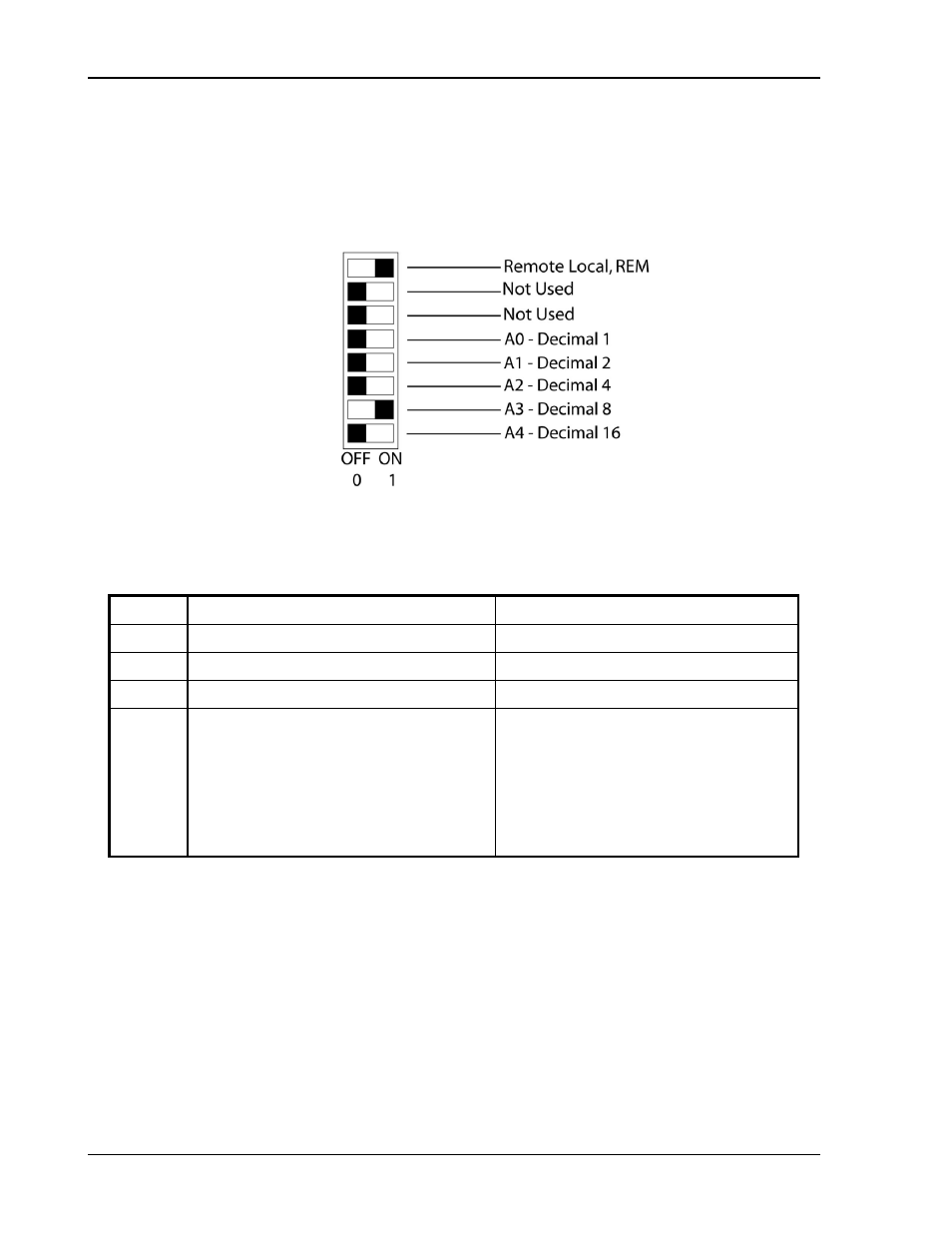
Figure 5-2 shows an example of switch settings for the DLM600 with the M6 option
and the DCS 1k and 1.2k power supplies with the M131 option, configured as an
auxiliary at channel 8, in remote mode.
Note: Only the Remote/Local switch is used for Ethernet.
Figure 5-2. Switch Configuration for M6 or M131 set to Channel 8
Table 5-1 Definitions of S1 Switch Settings
Switch
ON
OFF
S1-1
Remote control
Local control
S1-2
Not used.
Not used.
S1-3
Not applicable. Must be OFF.
Unit operates as an auxiliary unit.
S1-4–8
S1-4
S1-5
S1-6
S1-7
S1-8
Set channel number for unit in binary:
Binary 1 ON
Binary 2 ON
Binary 4 ON
Binary 8 ON
Binary 16 ON
(Channels 0 and 1 see note below.)
Binary 1 OFF
Binary 2 OFF
Binary 4 OFF
Binary 8 OFF
Binary 16 OFF
Note: Channel numbers 0 and 1 are invalid for any auxiliary device, because the M130
implementation of the SCPI language reserves channel 0 for the “global” address to
address all channels, and it reserves channel number 1 as the default number for the
master channel.