2 rear panel, 1 m130 (master) option, Rear panel -5 – AMETEK M130 User Manual
Page 23: M130 (master) option -5, Ee figure, 2, figure 2-3
Sorensen Ethernet Option
Configuration
M130/M131 Programming Manual
2-5
2.2 R
EAR
P
ANEL
2.2.1
M130
(M
ASTER
)
O
PTION
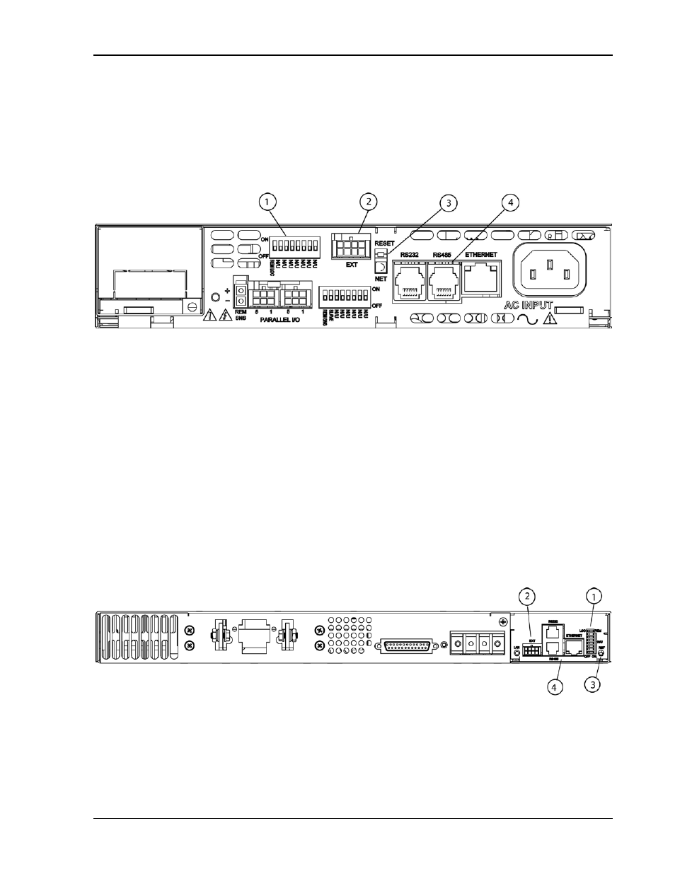
Figure 2-2 through Figure 2-4 display the pertinent rear panel components of a
typical M130 Ethernet option for the DLM600 and the DCS masters.
Figure 2-2. Typical Rear Panel of M130 Ethernet Option for DLM600
1 – Configuration Switch (for correct settings see Section 2.2.3)
2 – External User Control Signal Connector (see Section 2.3)
3 – Reset switch and green dual-purpose NET LED.
Reset switch (must be depressed until NET LED begins blinking, which could take
five or more seconds) returns configuration parameters to factory default settings
(see Section 1.3.2).
NET LED: when solid-lit, indicates Network Connectivity; blinking indicates
Instrument ID (See “Instrument ID” under Settings, Section 2.4.4). If the LED is
off, there is no Ethernet connection found by the power supply.
4 – Connections for Ethernet (RJ-45) with built-in 10/100 indicator (on right top of the
RJ45 connector) and an Activity indicator (on the left top). Also RJ-11 connectors
for RS232 and RS485.
Figure 2-3. Typical Rear Panel of M130 Option for DCS1k and DCS1.2k