5 board assembly diagram, Board assembly diagram -4 – SilentKnight 5808 User Manual
Page 21
Before You Begin Installing
151274-L8
3-4
3.5
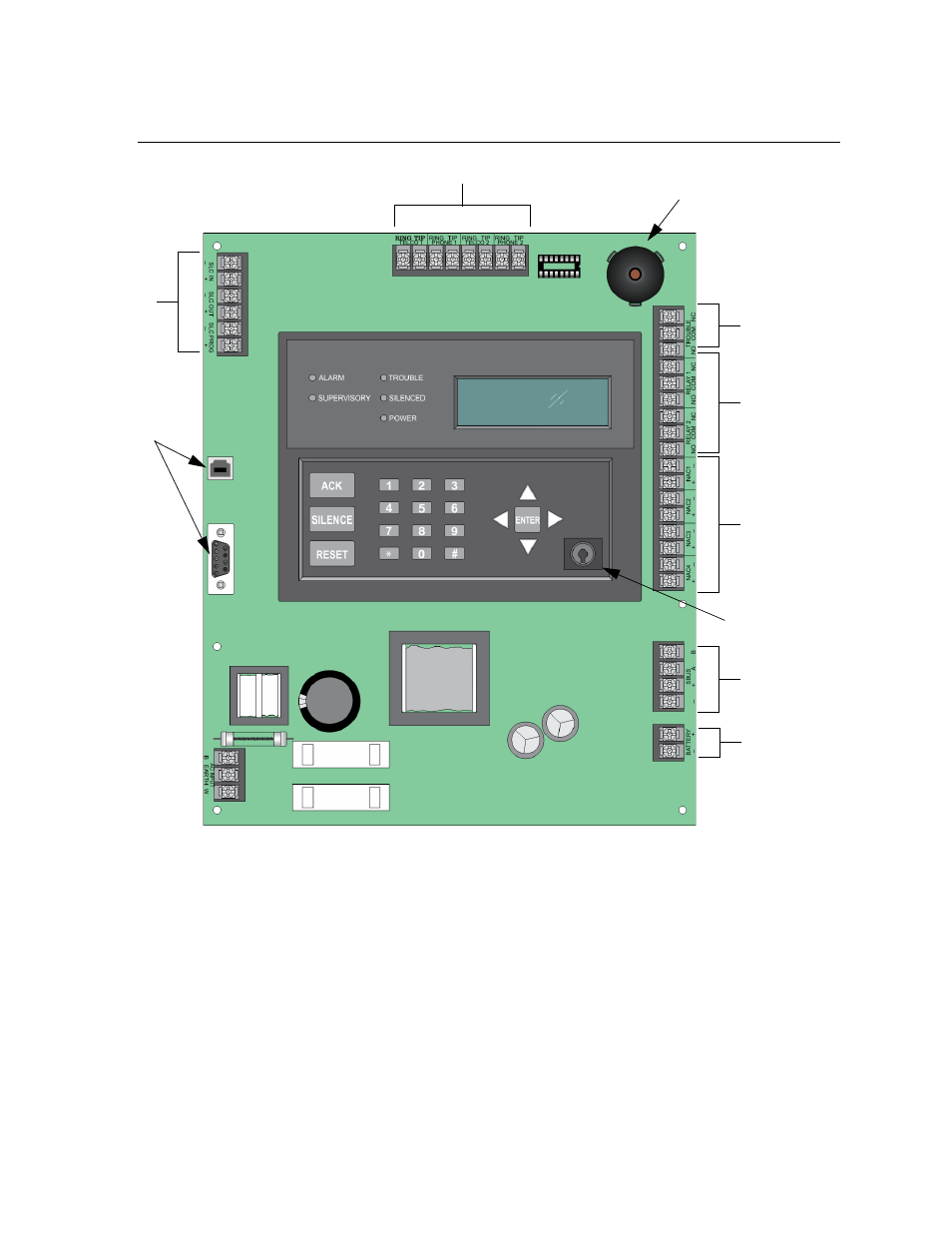
Board Assembly Diagram
Figure 3-2 Model 5808 Assembly
Figure 3-2 shows the circuit boards and annunciator. If you should need to remove the control board for repair,
remove the nine mounting screws (six on the circuit board and 3 on the heat-sink) which hold the control board
in the cabinet. Then lift the control board out of the cabinet.
On-board
Key Switch
Input
Annunciator
NAC/Aux
Power Circuits
Form C
Relays
Phone lines
SLC
In/Out
AC Power
Input
SBUS
Connections
Battery
Connections
Programming
Port
Form C
Trouble
Relay
See also other documents in the category SilentKnight Safety:
- 5104 Digital Alarm Communicator Transmitter 6 Zone (48 pages)
- 5128 Digital Alarm Communicator Transmitter (42 pages)
- 5217 10-Zone Expander for 5208 (2 pages)
- 5220 Direct Connect Module (2 pages)
- 5235 Remote Annunciator for 5208 (2 pages)
- 5280 Status Display Module for 5208 (2 pages)
- 5495 6A Distributed Power Module (52 pages)
- 5496 6A Intelligent Remote Power Supply (38 pages)
- 5499 9A Distributed Power Module (56 pages)
- 5600 (114 pages)
- 5660 Silent Knight Software Suite (28 pages)
- 5670 IntelliKnight Facility Management Software (24 pages)
- 5700 (180 pages)
- 5815RMK Remote Mounting Kit (2 pages)
- 5815XL Signal Circuit Expander (2 pages)
- 5820XL-EVS (236 pages)
- 5824 Serial/Parallel Module (2 pages)
- 5860/5860R Remote Annunciator (2 pages)
- 5865-3/5865-4 Remote LED Annunciator (2 pages)
- 5880 LED Driver Module (2 pages)
- 5883 Relay Interface Board (4 pages)
- 5895XL 6A Intelligent Remote Power Supply (56 pages)
- B200S Intelligent Sounder Base with CO Support (4 pages)
- B200S-LF - Low Frequency Intelligent Sounder Base (4 pages)
- B200SR Sounder Base (4 pages)
- B200SR-LF Low Frequency Intelligent Sounder Base (4 pages)
- B210LP 6 Mounting Base (2 pages)
- B224BI 6 Mounting Base w/Built-in Isolator (2 pages)
- B224RB 6 Mounting Base w/Built-in Relay (4 pages)
- B501 4 Mounting Base (2 pages)
- Central Station Monitoring List (1 page)
- Document Revision History (4 pages)
- EVS (74 pages)
- EVS-CE4 (2 pages)
- EVS-RVM (2 pages)
- EVS-VCM (2 pages)
- FFT (1 page)
- FFT-24 (2 pages)
- FFT-24 Installation (1 page)
- FFT-FPJ (1 page)
- FFT-HSC (1 page)
- FFT-STSS and FFT-STSR (2 pages)
- HFS-D (4 pages)
- HFS-MM (1 page)