3 electrical specifications, Electrical specifications -2 – SilentKnight 5808 User Manual
Page 19
Before You Begin Installing
151274-L8
3-2
3.3
Electrical Specifications
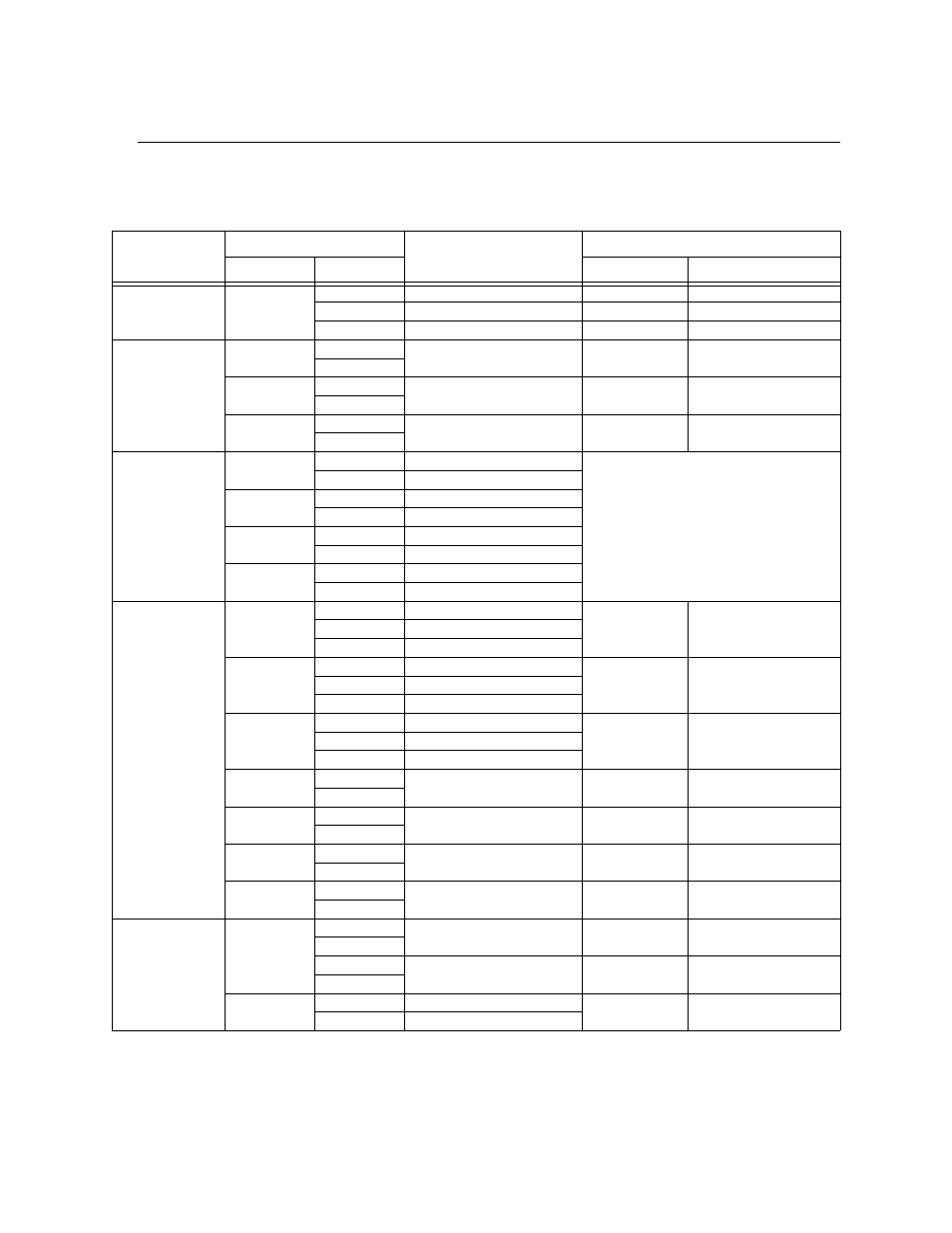
Table 3-1 list the terminal block on the 5808 as well as a description of the each individual terminal and their
respective electrical rating.
* Regulated/special application when used for releasing.
Table 3-1: Terminal Descriptions and Electrical Specifications
Terminal No.
Label
Description
Rating
Group
Individual
Voltage
Current
Terminal Block 1
AC INPUT
B
AC input (hot)
120 VAC, 60 Hz
3.6 A
Earth
Earth Ground
N/A
N/A
W
AC input (neutral)
120 VAC, 60 Hz
3.6 A
Terminal Block 2
SLC IN
–
Used for Class A installations
32 VDC
150 mA
+
SLC OUT
–
SLC terminals
32 VDC
150 mA
+
SLC PROG
–
Used for programming SLC
Detectors
32 VDC
150 mA
+
Terminal Block 3
TELCO 1
RING
Phone Line 1 Telco Ring
TIP
Phone Line 1 Telco Tip
PHONE 1
RING
Phone Line 1 Phone Ring
TIP
Phone Line 1 Phone Tip
TELCO 2
RING
Phone Line 2 Telco Ring
TIP
Phone Line 2 Telco Tip
PHONE 2
RING
Phone Line 2 Phone Ring
TIP
Phone Line 2 Phone Tip
Terminal Block 4
TROUBLE
NC
Normally closed relay contact
24 VDC
2.5 A, resistive
COM
Common terminal
NO
Normally open relay contact
RELAY 1
NC
Normally closed relay contact
24 VDC
2.5 A, resistive
COM
Common terminal
NO
Normally open relay contact
RELAY 2
NC
Normally closed relay contact
24 VDC
2.5 A, resistive
COM
Common terminal
NO
Normally open relay contact
NAC1*
–
Notification Appliance Circuit/
Auxiliary power
24 VDC
3.0 Amp NAC or Aux
power
+
NAC2*
–
Notification Appliance Circuit/
Auxiliary power
24 VDC
3.0 Amp NAC or Aux
power
+
NAC3*
–
Notification Appliance Circuit/
Auxiliary power
24 VDC
3.0 Amp NAC or Aux
power
+
NAC4*
–
Notification Appliance Circuit/
Auxiliary power
24 VDC
3.0 Amp NAC or Aux
power
+
Terminal Block 5
SBUS
B
SBUS Communication
5 VDC
100 mA
A
+
SBUS Power
24 VDC
1.0 A
–
BATTERY
+
To Positive battery terminal
24 VDC
Up to 35 Ah (see Section
4.3 for details)
–
To Negative battery terminal