7 16-bit up/down count pwm/output control mode, 7 16-bit up/down count pwm/output control mode -9, Maxq family user’s guide: maxq8913 supplement – Maxim Integrated MAXQ Family Users Guide: MAXQ8913 Supplement User Manual
Page 84
MAXQ Family User’s Guide:
MAXQ8913 Supplement
21-9
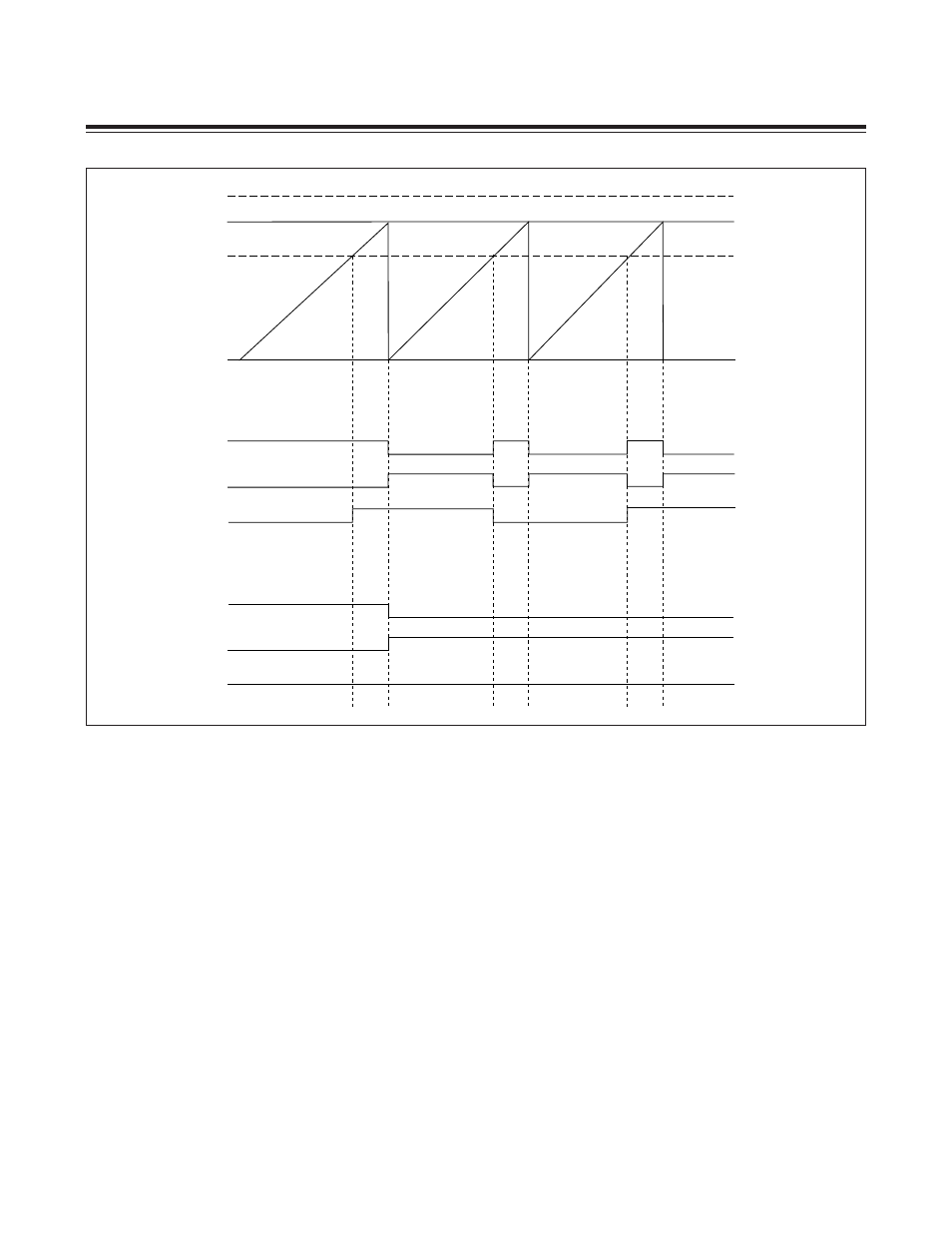
21.2.7 16-Bit Up/Down Count PWM/Output Control Mode
Figure 21-7 shows a functional diagram of the up/down-count PWM/output control mode. When the Timer B PWM/
output control functionality is enabled at the same time as the up/down-count autoreload mode, the TB0B pin no
longer controls the direction of counting. Instead, the up/down counting is controlled by logic inside the timer and is
determined by the value of the TBV count value register. When the timer is counting upward and reaches the value in
the TBR register, it reverses its direction of counting in the next cycle. When the timer is down counting and reaches
0000h, it reverses direction and begins counting up. This behavior and the results of the TBCS and TBCR bit setting
is shown in Figure 21-8.
The up/down-count PWM duty cycle is calculated as follows (where period = 2 x TBR Timer B clocks):
Set mode
= (TBR + TBC)/(2 x TBR)
Reset mode = TBC/(2 x TBR)
Toggle mode = TBC/TBR or (TBR - TBC)/TBR
The set and reset up/down-count PWM/output control modes effectively allow 17-bit resolution since set allows duty-
cycle variation R 50% with 50% of the period always being high, and reset allows duty-cycle variation P 50% with 50%
of the period always being low. The toggle mode provides a center-aligned 16-bit PWM with twice the period of the
pure up-counting autoreload mode.
Figure 21-6. Timer B PWM/Output Control Mode Waveform (Count Up)
TBC > TBR
TBC < TBR
TBR
0000
TBC < TBR
TBCS, TBCR =
TBC > TBR
TBCS, TBCR =
TB0B PIN
TB0B PIN
10 (SET)
10 (SET)
01 (SET)
11 (TOGGLE)
01 (SET)
11 (TOGGLE)
Maxim Integrated