Addendum to section 10: serial i/o module, 1 serial usart i/o pins and control registers, 2 serial usart code examples – Maxim Integrated MAXQ Family Users Guide: MAXQ8913 Supplement User Manual
Page 44: Maxq family user’s guide: maxq8913 supplement
MAXQ Family User’s Guide:
MAXQ8913 Supplement
10-1
ADDENDUM TO SECTION 10: SERIAL I/O MODULE
The MAXQ8913 provides one serial universal synchronous/asynchronous receiver-transmitter (USART) interface that
operates as described in the MAXQ Family User’s Guide.
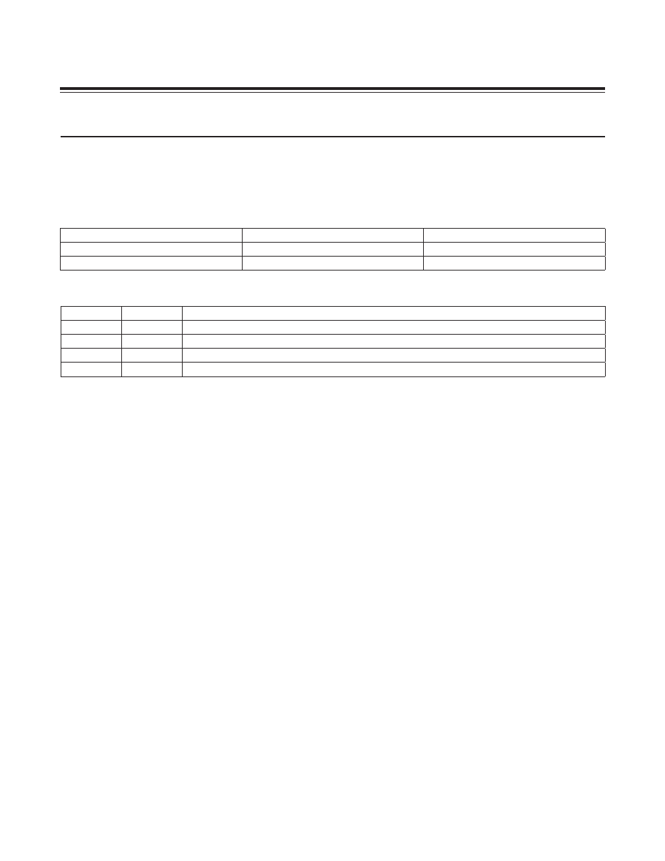
10.1 Serial USART I/O Pins and Control Registers
Table 10-1. Serial USART Input and Output Pins
Table 10-2. Serial USART Control Registers
10.2 Serial USART Code Examples
10.2.1 Serial USART Example: Echo Characters in 10-Bit Asynchronous Mode
move SCON.6, #1
; Set to mode 1 (10-bit asynchronous)
move SCON.4, #1
; Enable receiver
move SMD.1, #1
; Baud rate = 16 x baud clock
move PR, #007DDh
; P = 2^21 * 9600 / 10.000MHz
move SCON.0, #0
; Clear received character flag
move SCON.1, #0
; Clear transmit character flag
move Acc, #0Dh
call TxChar
move Acc, #0Ah
call TxChar
move Acc, #’>’
call TxChar
move Acc, #’ ‘
call TxChar
mainLoop:
call RxChar
call TxChar
jump mainLoop
SERIAL USART FUNCTION
PIN
MULTIPLEXED WITH GPIO
RX: Serial Receive
M3
P1.1
TX: Serial Transmit
N4
P1.0
REGISTER
ADDRESS
FUNCTION
SCON
M1[00h]
Serial Port Control Register. Serial port mode, receive enable, 9th bit control, and interrupt flags.
SBUF
M1[01h]
Serial Port Data Buffer. Input and output data buffer.
SMD
M1[08h]
Serial Port Mode Register. Controls baud rate, interrupt enable, and framing error detection.
PR
M1[09h]
Serial Port Phase Register. Contains counter reload value for baud-rate generation.
Maxim Integrated