6 16-bit up count pwm/output control mode, 6 16-bit up count pwm/output control mode -8, Maxq family user’s guide: maxq8913 supplement – Maxim Integrated MAXQ Family Users Guide: MAXQ8913 Supplement User Manual
Page 83
MAXQ Family User’s Guide:
MAXQ8913 Supplement
21-8
When the timer is not running (i.e., TRB = 0), the initial output state of the TB0B pin is established as low or high,
respectively, if the reset function (TBCR = 1,TBCS = 0) or set function (TBCR = 0, TBCS = 1) is configured. Invoking
the toggle function does not change the already defined starting state for TB0B, thus a fixed high or low starting state
can be defined for the toggle mode by first passing through the set or reset mode.
When the PWM/output control function is configured to the reset mode (TBCS = 0, TBCR = 1), clearing the TBC reg-
ister to 0000h or writing its value to something greater than the counting range (i.e., greater than the value in the TBR
register) effectively disables the reset operation, and produces a single pin set operation when an overflow occurs.
When the PWM/output control function is configured to the set mode (TBCS = 1, TBCR = 0), making TBC = TBR or
writing TBC’s value to something greater than the counting range disables the set operation, and produces a single
reset on TBR match. When the PWM/output control function is configured to toggle, loading the TBC register with a
value outside the counting range, to 0000h, or to the value in TBR disables the toggle function.
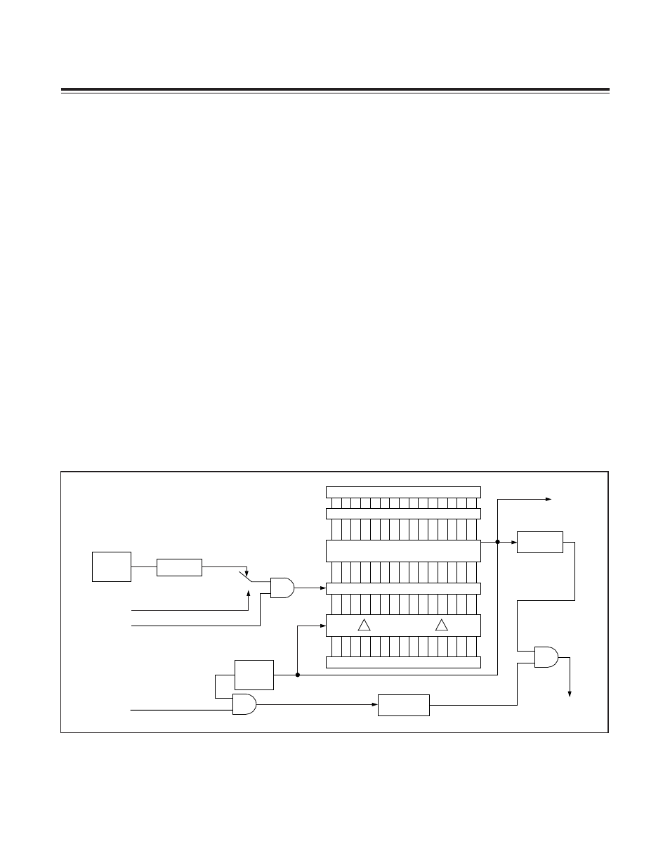
21.2.6 16-Bit Up Count PWM/Output Control Mode
Figure 21-5 shows a functional diagram of the up count with PWM/output control mode, and Figure 21-6 shows
example TB0B pin output waveforms. The set and reset modes provide similar functionality. They support up to 16-bit
resolution PWM with the ability to change the frequency using the TBR reload value. The toggle mode allows a 50%
duty-cycle waveform to be created (when the TBC register remains fixed with Timer B running). With the TBC register
value outside of the count range, the set and reset functions allow a timed clear or set of the TB0B pin without need of
polling or interrupting the CPU for manual port pin control.
Up-count set, reset PWM duty cycle is calculated as follows (where period = TBR + 1 Timer B clocks):
Set mode
= (TBR - TBC)/(TBR + 1)
Reset mode = TBC/(TBR + 1)
The period for the 50% duty-cycle signal generated in toggle mode is:
Toggle mode = 2 x (TBR + 1) Timer B Clock Periods
Figure 21-5. Up-Count PWM/Output Control Mode Block Diagram
15
0
15
0
TBR
TBC
TBV
0000h
FALLING
EDGE
EXENB = TBCN.3
TB0B PIN
TIMER B
INTERRUPT
0
1
TB0A PIN
TRB = TBCN.2
COMPARE
SYSTEM
CLOCK
C/TB = TBCN.15
EXFB = TBCN.6
TFB = TBCN.7
RELOAD
/CLK
2
(2 x TBPS[2:0])
TBPS[2:0] = TBCN[10:8]
Maxim Integrated