4 timer b clock output mode, 5 timer b pwm/output control functionality, Maxq family user’s guide: maxq8913 supplement – Maxim Integrated MAXQ Family Users Guide: MAXQ8913 Supplement User Manual
Page 82: Table 21-4. timer b pwm/output control function
MAXQ Family User’s Guide:
MAXQ8913 Supplement
21-7
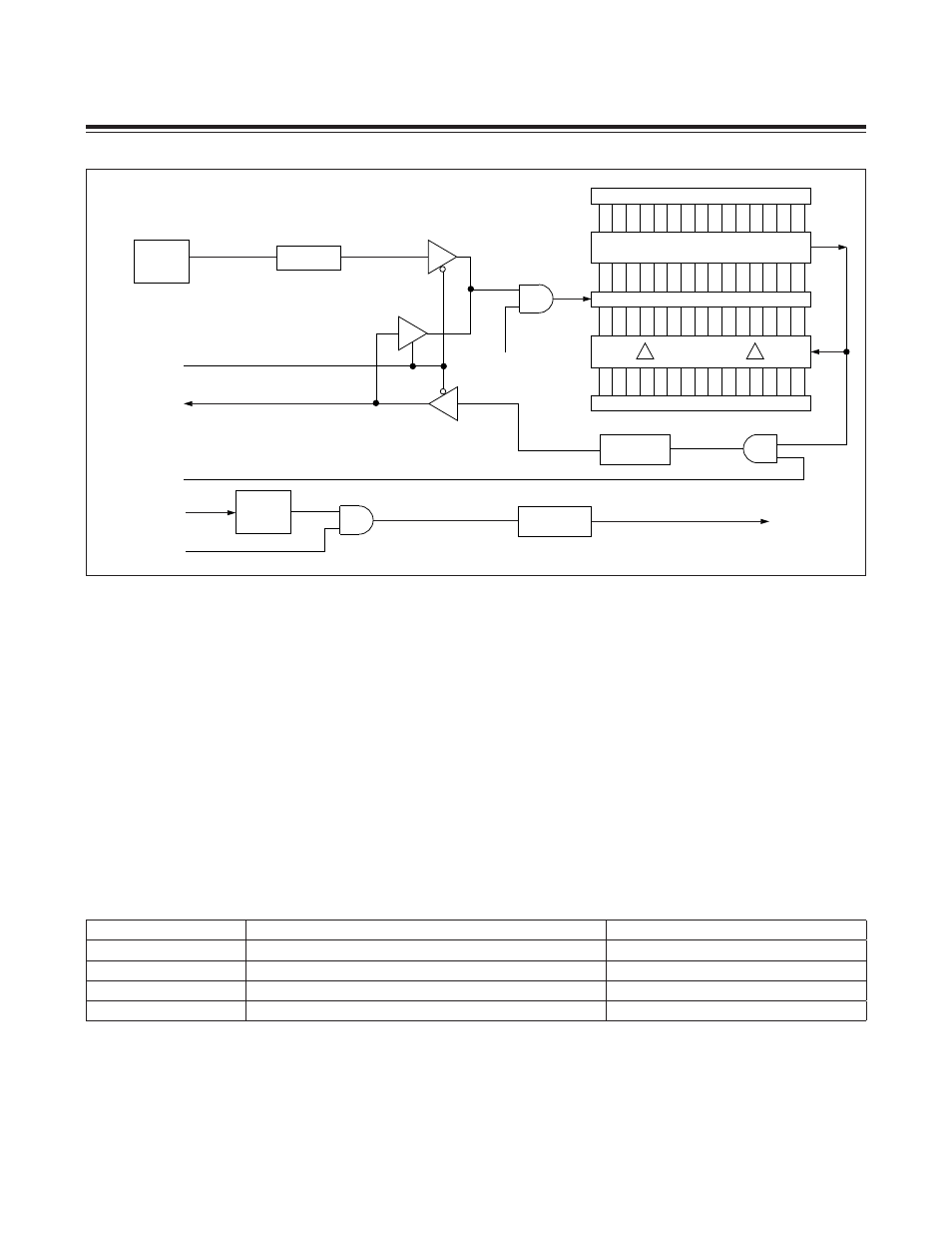
21.2.4 Timer B Clock Output Mode
Timer B can be configured to drive a clock output on the TB0A pin as shown in Figure 21-4. For the timer to operate
in this mode, the capture/reload select bit (CP/RLB = TBCN.0) and the counter/timer select bit (C/TB = TBCN.15) must
be cleared to 0, and the Timer B output-enable bit (TBOE = TBCN.5) ) must be set to 1. In this mode, the DCEN bit has
no effect. The clock signal output is a 50% duty-cycle square wave with a frequency given by the equation:
Clock Output Frequency = System Clock/(2 x TBR)
Therefore, for a system clock of 1MHz and a TBR register value of 0005h (arbitrary example), the clock output fre-
quency is 100kHz.
21.2.5 Timer B PWM/Output Control Functionality
The PWM/output control function is enabled whenever either of the TCBS or TBCR bits (TBCN[12:11]) is set to 1. Table
21-4 shows how these bits determine the specific operation.
Figure 21-4. Timer B Clock Output Mode Block Diagram
Table 21-4. Timer B PWM/Output Control Function
15
0
TBR
TBV
0000h
SYSTEM
CLOCK
TB0A PIN
TB0A PIN
TRB = TBCN.2
/CLK
C/TB = TBCN.15 = 0
DIVIDE BY 2
FALLING
EDGE
TB0B PIN
TIMER INTERRUPT
EXENB = TBCN.3
COMPARE
0
15
EXFB = TBCN.6
TBPS[2:0] = TBCN[10:8]
2
(2 x TBPS[2:0])
TBCS:TBCR
FUNCTION
INITIAL STATE (IF TRB = 0)
00
None (Disabled)
No change
01
Reset on TBC Match, Set on 0000h
Low
10
Set on TBC Match, Reset on TBR Match
High
11
Toggle on TBC Match
No change
Maxim Integrated