4 timer b timer value register (tbv, m2[0ah]), 4 timer b timer value register (tbv, m2[0ah]) -3, Maxq family user’s guide: maxq8913 supplement – Maxim Integrated MAXQ Family Users Guide: MAXQ8913 Supplement User Manual
Page 78
MAXQ Family User’s Guide:
MAXQ8913 Supplement
21-3
Bit 7: Timer B Overflow Flag (TFB). This bit is set when Timer B overflows from TBR or the count is equal to 0000h
in down-count mode. It must be cleared by software.
Bit 6: External Timer B Trigger Flag (EXFB). When configured as a timer (C/TB = 0), a negative transition on the
TB0B pin causes this flag to be set if (CP/RLB = EXENB = 1) or (CP/RLB = DCEN = 0 and EXENB = 1) or (CP/RLB =
0 and EXENB = 1 and TBCS:TBCR<>00b). When configured in any of these ways, this flag can be set independent of
the state of the TRB bit (e.g., EXFB can still be set on detection of a negative edge when TRB = 0).
When CP/RLB = 0 and DCEN = 1 and TBCS:TBCR = 00b, EXFB toggles whenever Timer B underflows or overflows.
Overflow/underflow condition is the same as described in the TFB bit description. In this mode, EXFB can be used as
the 17th timer bit and does not cause an interrupt. If set by a negative transition, this flag must be cleared by software.
Setting this bit to 1 forces a timer interrupt if enabled.
Bit 5: Timer B Output Enable (TBOE). Setting this bit to 1 enables the clock output function on the TB0A pin if C/TB =
0. Timer B rollovers do not cause interrupts. Clearing this bit to 0 allows the TB0A pin to function as either a standard
port pin or a counter input for Timer B.
Bit 4: Down-Count Enable (DCEN). This bit, in conjunction with the TB0B pin, controls the direction that Timer B
counts in 16-bit autoreload mode. Clearing this bit to 0 causes Timer B to count up only. Setting this bit to 1 enables
the up/down-counting mode (i.e., it causes Timer B to count up if the TB0B pin is 1 and to count down if the TB0B pin
is 0). When Timer B PWM-output mode functionality is enabled along with up/down counting (DCEN = 1), the up/down
count control of Timer B is controlled internally based upon the count in relation to the register settings. In the compare
modes, the DCEN bit controls whether the timer counts up and resets (DCEN = 0), or counts up and down (DCEN = 1).
Bit 3: Timer B External Enable (EXENB). Setting this bit to 1 enables the capture/reload function on the TB0B pin for
a negative transition (in up-counting mode). A reload results in TBV being reset to 0000h. Clearing this bit to 0 causes
Timer B to ignore all external events on TB0B pin. When operating in autoreload mode (CP/RLB = 0) with the PWM
output functionality enabled, enabling the TB0B input function (EXENB = 1) allows PWM output negative transitions to
set the EXFB flag, however, no reload occurs as a result of the external negative-edge detection.
Bit 2: Timer B Run Control (TRB). This bit enables Timer B operation when set to 1. Clearing this bit to 0 halts Timer
B operation and preserves the current count in TBV.
Bit 1: Enable Timer B Interrupt (ETB). Setting this bit to 1 enables the interrupt from the Timer B TFB and EXFB flags
in TBCN. In Timer B clock-output mode (TBOE = 1), the timer overflow flag (TFB) is still set on an overflow, however,
the TBOE = 1 condition prevents this flag from causing an interrupt when ETB = 1.
Bit 0: Capture/Reload Select (CP/RLB). This bit determines whether the capture or reload function is used for Timer
B. Timer B functions in an autoreload mode following each overflow/underflow. See the TFB bit description for overflow/
underflow condition. Setting this bit to 1 causes a Timer B capture to occur when a falling edge is detected on the
TB0B pin if EXENB is 1. Clearing this bit to 0 causes an autoreload to occur when Timer B overflow or a falling edge
is detected on TB0B pin if EXENB is 1. It is not intended that the Timer B compare functionality should be used when
operating in capture mode.
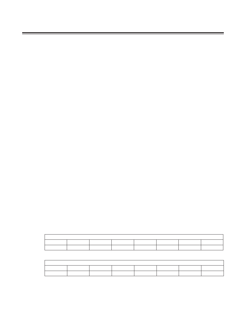
21.1.4 Timer B Timer Value Register (TBV, M2[0Ah])
Bits 15:0: Timer B Value Register. This register is used to load and read the 16-bit Timer B value.
Bit #
15
14
13
12
11
10
9
8
Name
TBV
Reset
0
0
0
0
0
0
0
0
Access
rw
rw
rw
rw
rw
rw
rw
rw
Bit #
7
6
5
4
3
2
1
0
Name
TBV
Reset
0
0
0
0
0
0
0
0
Access
rw
rw
rw
rw
rw
rw
rw
rw
Maxim Integrated